The force vector will be calculated according to:
or written in components:
Defines a property or a coupling between masses.
The user can choose to define the coupling with main command `coupl` or `coupl_para`. If defined with command `coupl` the coupling forces will be calculated sequentially together with the other commands in the model. If defined with command `coupl_para` the coupling forces will be calculated in parallel in the end of every timestep.
The OMP_NUM_THREADS environment variable specifies the number of threads to use for parallel regions. If OMP_NUM_THREADS is undefined, all threads in the CPU will be used. If you want to limit the number of used threads you can start a calculation in program CALC according to the following example:
OMP_NUM_THREADS=4 tsim runf/tang_ideal.tsimf
The underscore letter "_" in coupling names has a very special meaning. See Fallback Values
E.g. The underscore letter can be used in the following way:
| _111l or _111r | => | Wheel specific name |
| _111 | => | Axle specific name |
| _11l or _11r | => | Bogie side specific name |
| _11 | => | Bogie specific name |
| _1 | => | Vehicle specific name |
| _ | => | Fallback value for the whole train-set if no specific name can be found |
Please start to look in the theory manual, for the definition of deformations in couplings.
Available couplings:
| p_lin | Defines a linear property |
| p_lin36 | Defines a linear 6x6-matrix property |
| p_lin144 | Defines a linear 12x12-matrix property |
| p_nlin | Defines a non-linear property |
| p_nlin_s | Defines an asymmetric non-linear property |
| p_nlin_t | Defines a non-linear property given by tangential values |
| p_nlin_st | Defines an asymmetric non-linear property given by tangential values |
| p_kfrkc | Property designed for coupling kfrkc |
| beam_1 | Defines an Euler-Bernoulli beam connected to many masses |
| beam_3 | Defines an Euler-Bernoulli beam with variable bending stiffness |
| beam_4 | Similar to beam_3 but takes more effects into consideration. |
| c | Defines damper with a pre-defined property |
| c_l | Damper similar to c, oriented a small angle relative to esys |
| c_r | Damper similar to c, oriented a large angle relative to esys |
| c_vs_d | Defines a displacement-controlled damper |
| c12_b1 | Defines a damping coupling between two masses of type m_rigid_12 |
| c12_f | Defines a damping coupling between two masses of type m_rigid_12 |
| c_magic_1 | Defines a rolling contact between two masses according to the Magic Formula |
| creep_contact_1 | Defines a rolling contact between two masses according to CONTACT |
| creep_contact_6 | A wheel/rail-contact that utilizes the new features in CONTACT v23.2 |
| creep_fasim_1 | Defines a rolling contact between two masses. The normal contact is solved in a linear spring. The tangential contact is solved with Kalker's fasim routine. |
| creep_fasim_2 | Similar to creep_fasim_1, but the creepages are modulated according formulas developed by: Maksym Spiryagin , Oldrich Polach & Colin Cole; Vehicle System Dynamics, 13 Aug 2013. |
| creep_fasim_4 | Similar to creep_fasim_1, but this wheel/rail-coupling uses the wheel and rail profiles directly. |
| creep_fastrip_1 | Defines a rolling contact between two masses according to ANALYN and FaStrip. |
| creep_fastrip_3 | Defines a rolling contact between two masses according using FaStrip for the tangential problem. |
| creep_lookuptable_1 | Defines a rolling contact between two masses |
| creep_lookuptable_2 | Defines a rolling contact between two masses |
| creep_polach_2 | Defines a rolling contact between two masses. The normal contact is solved in a linear spring. The tangential contact is solved with O.Polach's ADH-routine. |
| creep_tanel_springs_1 | Defines a rolling contact between two masses |
| coupler_1 | Car-car coupler, buffer and/or draw-gear |
| coupler_2 | Car-car coupler, buffer and/or draw-gear |
| derailm_2 | Defines a contact element between two bodies |
| k, k_preZ | Defines stiffness with a pre-defined property |
| k_l, k_l_preZ | Similar to coupl k, but rotated a small angle relative to esys |
| k_r, k_r_preZ | Similar to coupl k, but rotated a large angle relative to esys |
| k12_b1 | Defines a stiffness coupling between two masses of type m_rigid_12 |
| k12_f | Defines a stiffness coupling between two masses of type m_rigid_12 |
| k3, k3_preZ | Defines stiffness with 3 pre-defined properties |
| k3_l, k3_l_preZ | Similar to coupl k3, but rotated a small angle relative to esys |
| k3_r, k3_r_preZ | Similar to coupl k3, but rotated a large angle relative to esys |
| km, km_preZ | Similar to coupl k, but the user can control if the coupling shall generate moments on attached masses or not |
| km_l, km_l_preZ | Similar to coupl km, but rotated a small angle relative to esys |
| km_r, km_r_preZ | Similar to coupl km, but rotated a large angle relative to esys |
| k_air3_exp | A coupling for modeling airbags with exponential smooth friction in the horizontal plane. |
| k_air3_mawa | A coupling for modeling airbags in railway vehicles, using equations for viscous flow in pipes in vertical direction. |
| k_air3_mawa2 | A coupling for modeling airbags as in coupling k_air3_mawa, but with two auxiliary air reservoirs in parallel. |
| k_air4 | A coupling for modeling of airbags. |
| k_coil3 | A coupling for modeling of vertically standing coil springs. |
| kc | Defines a spring in series with a damper. |
| kce | Defines a spring in series with a damper with an exponent factor. |
| kckc | Defines a coupling consisting of two dampers and two springs. The first spring and damper are connected in parallel with each other |
| kf | Defines a friction block with series flexibility |
| kf_l | Similar to coupl kf, but rotated a small angle relative to esys |
| kf_r | Similar to coupl kf, but rotated a large angle relative to esys |
| kf2 | Defines a two-dimensional friction block with two perpendicular serial flexibilities |
| kf2_l | Similar to coupl kf2, but rotated a small angle relative to esys |
| kf2_r | Similar to coupl kf2, but rotated a large angle relative to esys |
| kf3 | Defines a three-dimensional friction block with three perpendicular serial flexibilities |
| kfrkc | Defines a coupling with smooth friction and viscous damping |
| kf_exp1 | Defines a coupling comprising a stiffness with exponential friction |
| kf_exp2 | A stiffness coupling with a exponential shaped friction added on |
| kf_exp3 | A stiffness coupling with a smooth friction added on |
| m_flex_1 | Links a coupling to a flexible body |
| m_flex_m6 | Links a coupling to a flexible body with a moving attachment point |
| cuser# | Defines a coupling whose properties are defined in an own supplied subroutine CUSER# (# is a number between 0 and 9) |
c_type = `p_lin`
Defines a linear coupling property.
coupl p_lin `p_name' +-`F0 +-`v1
| p_name | = | Assigning a name to this property. |
| F0 | = | The force which the property will produce on zero displacement.
F0 is used to define a preloaded spring.
Positive value in F0 will lead to a positive
force on body no.1 at zero displacement. F0 has no significance when the coupling property is used in dampers. The value can either be constant or a previously defined variable. By using a variable, this coupling property can describe a non-linear property or an active coupling element. |
| v1 | = | Stiffness or damping values of the defined property. The value can either be constant or a previously defined variable. By using a variable, this coupling property can describe a non-linear property or an active coupling element. |
Variables generated in main memory:
| p_name.F0 | = | F0 | = | Force on zero displacement. |
| p_name.v1 | = | v1 | = | The property value of the coupling |
c_type = `p_lin36`
Defines a 6x6 dimensional linear coupling matrix,
and a vector which specifies the coupling's preload forces on zero displacement.
If components of the coupling matrix or the preload vector consists of variables,
then a non-linear coupling matrix can be modeled.
The force vector will be calculated according to:
![]()
or written in components:
coupl p_lin36 `p_name' +-`F0(1:6) +-`k(1:6,1:6)
| p_name | = | Assigning a name to this property. |
| F0 | = | Six-dimensional force vector according to the formula above.
F0 is used to define a preloaded spring.
Positive values in F0 will lead to positive
forces on body no.1 at zero displacement. F0 has no significance when the coupling property is used in dampers. The values can either be constant or previously defined variables. By using a variable, this coupling property can describe a non-linear property or an active coupling element. |
| k | = | 6x6-dimensional coupling matrix. The data is read in rows k(1,1), k(1,2), k(1,3) ,,, etc. |
| p_name.F0x | = | Preload force in x-direction. |
| p_name.F0y | = | Preload force in y-direction. |
| p_name.F0z | = | Preload force in z-direction. |
| p_name.F0f | = | Preload moment in f-direction. |
| p_name.F0k | = | Preload moment in k-direction. |
| p_name.F0p | = | Preload moment in p-direction. |
| p_name.xx | = | The xx-component of the coupling matrix. |
| p_name.xy | = | The xy-component of the coupling matrix. |
| p_name.xz | = | The xz-component of the coupling matrix. |
| p_name.xf | = | The xf-component of the coupling matrix. |
| . . . | = | . . . . . . . . . |
| . . . | = | . . . . . . . . . |
| p_name.pp | = | The pp-component of the coupling matrix. |
c_type = `p_lin144`
Defines a 12x12 dimensional linear coupling matrix,
and a vector which specifies the coupling's prestressing forces on zero displacement.
If components of the coupling matrix or the preload vector
consists of variables, then a non-linear coupling matrix can be modeled.
The force vector is calculated according to the following formula:
or written in components:
coupl p_lin144 `p_name' +-`F0(1:12) +-`k(1:12,1:12)
| p_name | = | Assigning a name to this property. |
| F0 | = | Force vector which is added to the output data. |
| k | = | Coupling matrix, the data is read in rows. |
Variables generated in the main memory:
| p_name.F1x | = | Force Fx on body 1 when delta_x1 = 0. |
| p_name.F1y | = | Force Fy on body 1 when delta_y1 = 0. |
| p_name.F1z | = | Force Fz on body 1 when delta_z1 = 0. |
| p_name.F1f | = | Force Ff on body 1 when delta_f1 = 0. |
| p_name.F1k | = | Force Fk on body 1 when delta_k1 = 0. |
| p_name.F1p | = | Force Fp on body 1 when delta_p1 = 0. |
| p_name.F2x | = | Force Fx on body 2 when delta_x2 = 0. |
| p_name.F2y | = | Force Fy on body 2 when delta_y2 = 0. |
| p_name.F2z | = | Force Fz on body 2 when delta_z2 = 0. |
| p_name.F2f | = | Force Ff on body 2 when delta_f2 = 0. |
| p_name.F2k | = | Force Fk on body 2 when delta_k2 = 0. |
| p_name.F2p | = | Force Fp on body 2 when delta_p2 = 0. |
| p_name.11 | = | x1x1-component of the stiffness matrix. |
| p_name.12 | = | x1y1-component of the stiffness matrix. |
| p_name.13 | = | x1z1-component of the stiffness matrix. |
| p_name.14 | = | x1f1-component of the stiffness matrix. |
| p_name.15 | = | x1k1-component of the stiffness matrix. |
| p_name.16 | = | x1p1-component of the stiffness matrix. |
| p_name.17 | = | x1x2-component of the stiffness matrix. |
| p_name.18 | = | x1y2-component of the stiffness matrix. |
| p_name.19 | = | x1z2-component of the stiffness matrix. |
| p_name.1A | = | x1f2-component of the stiffness matrix. |
| p_name.1B | = | x1k2-component of the stiffness matrix. |
| p_name.1C | = | x1p2-component of the stiffness matrix. |
| p_name.21 | = | y1x1-component of the stiffness matrix. |
| p_name.22 | = | y1y1-component of the stiffness matrix. |
| . . . | = | . . . . . . . . . |
| . . . | = | . . . . . . . . . |
| . . . | = | . . . . . . . . . |
| p_name.CB | = | p2k2-component of the stiffness matrix. |
| p_name.CD | = | p2p2-component of the stiffness matrix. |
c_type = `p_nlin`
Defines a non-linear coupling property, built-up of a number of force-displacement value-pairs.
 coupl p_nlin `p_name' +-`value0
                      (+-`)v_pairs(*)
| p_name | = | Assigning a name to this property. |
| value0 | = | In addition to the coupling force produced by v_pairs,
an extra force can be given in value0.
Value0 is used to define a preloaded spring or a spring with the force of gravity acting through it.
Positive value in value0 will lead to a positive force acting on body no.1 at zero displacement. Value0 has no significance when the coupling property is used in dampers. |
| v_pairs | = | The value pair which the property shall have.
The value pairs are described with x and y coordinates in the following order:
x1, y1, x2, y2, x3,,,, etc. The end of the input is marked by entering a new valid main command according to the list under the Input Data Menu. The value pairs must be an even number otherwise an error will occur. If the displacement is to the left of x(1) or to the right of x(n), the force will be extrapolated based on the gradient of the line between the outermost x-value and the second outermost x-value. The x-values in the value pair must be ascending, otherwise an error will occur, and the point will be ignored. |
| p_name.F0 | = | Force at zero displacement. |
| p_name.nb | = | Number of breakpoints. |
| p_name.x1 | = | Displacement value for point no. 1. |
| p_name.y1 | = | The coupling force at displacement no. 1. |
| p_name.x2 | = | Displacement value for point no. 2. |
| p_name.y2 | = | The coupling force at displacement no. 2. |
| p_name.x3 | = | Displacement value for point no. 3. |
| . . . . | = | . . . . . . . . . . . . . |
| . . . . | = | . . . . . . . . . . etc. |

c_type = `p_nlin_s`
Defines an asymmetric non-linear coupling property, whose properties in positive deformations (velocity) are described in v_pairs below. The same force, but with the opposite sign, are given for negative deformations (velocity).
 coupl p_nlin_s `p_name' +-`value0
                        (+-`)v_pairs(*)
| p_name | = | Assigning a name to this property. |
| value0 | = | The force which the property will produce on zero displacement. Value0 is used to define a preloaded spring or a spring with the force of gravity acting through it. Positive value in value0 will lead to a positive force on body no.1 at zero displacement. Value0 is redundant if the coupling property is used in dampers. |
| v_pairs | = | The value pair which the property shall have.
The value pairs are described with x and y coordinates in the following order:
x2, y2, x3, y3, x4,,,, etc. The first coordinate (x1,y1) is already predefined and equal to (0.,0.). The end of the input is marked by entering a new valid main command according to the list under item 3.1). The value pairs must be an even number otherwise an error will occur. If the input variable is larger than the breakpoint for the last x-value x(n), the output will be extrapolated based on the gradient of the line between the outermost x-value and the second outermost x-value. The x-values in the value pair must be in ascending sequence, otherwise an error will occur, and the point will be ignored in the input phase. |
| p_name.F0 | = | Force at zero displacement. |
| p_name.nb | = | Number of breakpoints. |
| p_name.x1 | = | Displacement value for the initial point is predefined and equal to 0. |
| p_name.y1 | = | The coupling force for the initial point is predefined and equal to 0. |
| p_name.x2 | = | Displacement value for point no. 2. |
| p_name.y2 | = | The coupling force at displacement no. 2. |
| p_name.x3 | = | Displacement value for point no. 3. |
| . . . . | = | . . . . . . . . . . . . . |
| . . . . | = | . . . . . . . . . . etc. |

c_type = `p_nlin_t`
Defines a non-linear coupling property, built-up of tangential gradients and breakpoints given by the values listed below. As the stiffness curve is only described by gradients, the vertical position of the curve is not defined. Therefore the user must start the input data string with a reference point (x-ref,y-ref) which the curve shall pass through.
 coupl p_nlin_t  `p_name',
                 (+-`)x-ref,  (+-`)y-ref,
                 (+-`)values(*)
| p_name | = | Assigning a name to this property. |
| x-ref | = | X-value of the reference point. The argument for x-ref may either be a constant or a variable. If a variable is read, the variable's value will be retrieved and will be stored in p_name.xl, but if the variable's value is changed during the calculation process, it will not affect the property p_name. The original values in p_name.xl will remain. |
| y-ref | = | Y-value of the reference point. The argument for y-ref may either be a constant or a variable. If a variable is read, the variable's value will be retrieved and will be stored in p_name.yl, but if the variable's value is changed during the calculation process, it will not affect the property p_name. The original values in p_name.yl will remain. |
| values | = | The gradients and breakpoints which the property will have.
The values are described by gradient, breakpoint, gradient, breakpoint,,, in the following order: v1, x2, v2, x3, v3,,,, etc. The x-values must be increasing starting with the most negative point, and end with the most positive point. The input will be concluded by giving a new valid main command according to the list under item 3.1). The number of values must be odd otherwise an error will occur. The values will both begin and end with gradients. These gradients will apply when the displacement lies outside the outermost breakpoints. The breakpoints must be in ascending sequence otherwise an error print will occur, and the point will be ignored during the input phase. |
| p_name.nb | = | Number of breakpoints. |
| p_name.x1 | = | X-reference point. |
| p_name.y1 | = | Y-reference point. |
| p_name.v1 | = | First tangential gradient |
| p_name.x2 | = | First breakpoint |
| p_name.v2 | = | Second tangential gradient |
| p_name.x3 | = | Second breakpoint |
| p_name.v3 | = | Third tangential gradient |
| . . . . | = | . . . . . . . . . . . . . |
| . . . . | = | . . . . . . . . . . etc. |
c_type = `p_nlin_st`
Defines an asymmetric non-linear coupling property, built-up of tangential gradients and breakpoints given by the values listed below. As the stiffness curve is only described by gradients and breakpoints, the curve must be related to a fixed point given by a force and displacement. For this case c_type = `p_nlin_st`, the fixed point will be (displacement=0, force=value0).
 coupl p_nlin_st `p_name',
                 (+-`)value0, (+-`)values(*)
| p_name | = | Assigning a name to this property. |
| value0 | = | The force which the property will produce on zero displacement.
Value0 is used to define a preloaded spring or a spring with the force of gravity acting through it.
Positive value in value0 will lead to a positive force on body no.1 at zero displacement. Value0 has no significance when the coupling property is used in dampers. |
| values | = | The gradients and breakpoints which the property will have.
The values are described by gradient, breakpoint, gradient, breakpoint,,, in the following order: v1, x1, v2, x2, v3,,,, etc. The input is ended by giving a new valid main command according to the list under item 3.1). The number of values must be odd otherwise the program will stop and an error message will be printed. The values must both begin and end with gradients. These gradients will apply when the displacement lies outside the outermost breakpoints. All breakpoints must be positive and in ascending order otherwise a warning message will be printed, and the point will be ignored during the reading phase. The argument in the values can contain both constants and variables. If a variable is read, the variable's value will be retrieved and stored under the property's memory position, but if the variable's value is changed during the calculation process, it will not affect the property p_name. The original values will remain. |
| p_name.F0 | = | Force at zero displacement. |
| p_name.nb | = | Number of breakpoints. |
| p_name.v1 | = | Tangential gradient through x=0. |
| p_name.x2 | = | Displacement value for point no. 2. |
| p_name.v2 | = | Tangential gradient after point 2. |
| p_name.x3 | = | Displacement value for point no. 3. |
| p_name.v3 | = | Tangential gradient after point 3. |
| . . . . | = | . . . . . . . . . . . . . |
| . . . . | = | . . . . . . . . . . etc. |
c_type = `p_kfrkc`
Defines the parameters to the non-linear coupling kfrkc.
coupl p_kfrkc `p_name' +-`F0 +-`ke +-`Ffm +-`x2 +-`kv +-`c
| p_name | = | Assigning a name to this property. |
| F0 | = | The force which the property will have on zero displacement. Positive value gives positive force on body no. 1 at zero displacement. |
| ke | = | Stiffness for the elastic part of the coupling. |
| Ffm | = | Maximum friction force for the friction part of the coupling. |
| x2 | = | Displacement, relative initial position, when half the maximum friction force has been reached. |
| kv | = | Serial stiffness for the viscous part of the coupling. |
| c | = | Damping coefficient for the viscous part of the coupling. |
| p_name.F0 | = | Force F0 |
| p_name.ke | = | Stiffness ke |
| p_name.Ffm | = | Force Ffm |
| p_name.x2 | = | Displacement x2 |
| p_name.kv | = | Stiffness kv |
| p_name.c | = | Damping c |
c_type = `beam_1`
Defines an Euler-Bernoulli beam connected to many masses
 coupl beam_1  `c_name' `dire' +-`EI
                +-`nSuspMass
                m_name_s1  +-`m_name_s1.A +-`m_name_s1.B +-`m_name_s1.H  +-`m_name_s1.k
                m_name_s2  +-`m_name_s2.A +-`m_name_s2.B +-`m_name_s2.H  ,,, etc.
                +-`nRigidMass
                m_name_r1  +-`m_name_r1.A +-`m_name_r1.B +-`m_name_r1.H
                m_name_r2  +-`m_name_r2.A +-`m_name_r2.B    ,,, etc.
| c_name | = | Name of the coupling to be created. |
| dire | = | Working direction for the beam. Valid directions are: `x`, `y` and `z`. |
| EI | = | Young's modulus times area moment of inertia. |
| nSuspMass | = | Number of suspended masses connected to the beam. |
| m_name_s1 | = | Name of first suspended mass |
| m_name_s1.A | = | Attachment point for first suspended mass in longitudinal direction |
| m_name_s1.B | = | Attachment point for first suspended mass in lateral direction |
| m_name_s1.H | = | Attachment point for first suspended mass in vertical direction |
| m_name_s1.k | = | Stiffness between first mass and beam |
| m_name_s2 | = | Name of second suspended mass |
| etc. | = | etc. |
| nRigidMass | = | Number of rigidly attached masses. |
| m_name_r1 | = | Name of first unsuspended mass |
| m_name_r1.A | = | Attachment point for first unsuspended mass in longitudinal direction |
| m_name_r1.B | = | Attachment point for first unsuspended mass in lateral direction |
| m_name_r1.H | = | Attachment point for first unsuspended mass in vertical direction |
| m_name_r2 | = | Name of second unsuspended mass |
| etc. | = | etc. |
Variables generated in the main memory:
Input variables:
| c_name.EI | = | Young's modulus times area moment of inertia. |
| c_name.NsMass | = | Number of suspended masses. |
| c_name.sMass? | = | The number of the suspended mass. |
| c_name.AsM? | = | Longitudinal position of attachment point for a suspended mass. |
| c_name.BsM? | = | Lateral position of attachment point for a suspended mass. |
| c_name.HsM? | = | Vertical position of attachment point for a suspended mass. |
| c_name.ksM? | = | Stiffness between attachment point and the suspended mass. |
| c_name.NrMass | = | Number of unsuspended masses. |
| c_name.rMass¿ | = | The number of the unsuspended mass. |
| c_name.ArM¿ | = | Longitudinal position of attachment point for an unsuspended mass. |
| c_name.BrM¿ | = | Lateral position of attachment point for an unsuspended mass. |
| c_name.HrM¿ | = | Vertical position of attachment point for an unsuspended mass. |
Output variables:
| c_name.ps | = | Position of beam in attachment point for a suspended mass. |
| c_name.ds | = | Deflection of the series spring m_name_s?.k, where m_name_s? is a suspended mass. |
| c_name.Fs | = | Force in series spring m_name_s?.k, where m_name_s? is a suspended mass. |
| c_name.dr | = | Position of attachment point for an unsuspended mass. |
| c_name.fr | = | Angle of attachment point for an unsuspended mass. |
| c_name.Fr | = | Force between an unsuspended mass and beam. |
| – | Detailed rail model. |
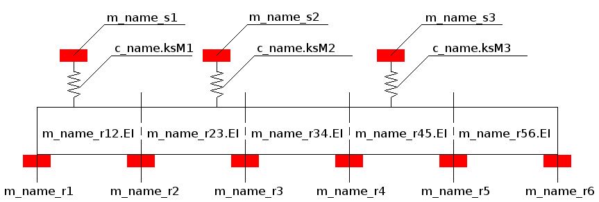
c_type = `beam_3`
Defines an Euler-Bernoulli beam connected to many masses. This beam is very similar to coupl beam_1 above, with the extension that this beam handles a bending stiffness that varies along the beam.
 coupl beam_3  `c_name' `dire'
                nSuspMass
                m_name_s1  (+-`)c_name.AsM1 (+-`)c_name.BsM1 (+-`)c_name.HsM1  (+-`)c_name.ksM1
                m_name_s2  (+-`)c_name.AsM2 (+-`)c_name.BsM2 (+-`)c_name.HsM2  ,,, etc.
                nRigidMass
                m_name_r1  (+-`)m_name_r1.A (+-`)m_name_r1.B (+-`)m_name_r1.H
                m_name_r2  (+-`)m_name_r2.A (+-`)m_name_r2.B (+-`)m_name_r2.H (+-`)m_name_r12.EI
                m_name_r3  (+-`)m_name_r3.A (+-`)m_name_r3.B (+-`)m_name_r3.H (+-`)m_name_r23.EI
                m_name_r4  (+-`)m_name_r4.A (+-`)m_name_r4.B    ,,, etc.
| c_name | = | Name of the coupling to be created. |
| dire | = | Working direction for the beam. Valid directions are `y` and `z`. |
| nSuspMass | = | Number of suspended masses connected to the beam. |
| m_name_s1 | = | Name of first suspended mass |
| c_name.AsM1 | = | Attachment point for first suspended mass in longitudinal direction |
| c_name.BsM1 | = | Attachment point for first suspended mass in lateral direction |
| c_name.HsM1 | = | Attachment point for first suspended mass in vertical direction |
| c_name.ksM1 | = | Stiffness between mass m_name_s1 and beam |
| m_name_s2 | = | Name of second suspended mass |
| c_name.AsM2 | = | Attachment point for second suspended mass in longitudinal direction |
| etc. | = | etc. |
| nRigidMass | = | Number of rigidly attached masses. |
| m_name_r1 | = | Name of first unsuspended mass |
| m_name_r1.A | = | Attachment point for first unsuspended mass in longitudinal direction |
| m_name_r1.B | = | Attachment point for first unsuspended mass in lateral direction |
| m_name_r1.H | = | Attachment point for first unsuspended mass in vertical direction |
| m_name_r2 | = | Name of second unsuspended mass |
| m_name_r2.A | = | Attachment point for second unsuspended mass in longitudinal direction |
| m_name_r2.B | = | Attachment point for second unsuspended mass in lateral direction |
| m_name_r2.H | = | Attachment point for second unsuspended mass in vertical direction |
| m_name_r12.EI | = | Young's modulus times area moment of inertia for section 1-2. |
| m_name_r3 | = | Name of third unsuspended mass |
| m_name_r3.A | = | Attachment point for third unsuspended mass in longitudinal direction |
| m_name_r3.B | = | Attachment point for third unsuspended mass in lateral direction |
| m_name_r3.H | = | Attachment point for third unsuspended mass in vertical direction |
| m_name_r23.EI | = | Young's modulus times area moment of inertia for section 2-3. |
| m_name_r4 | = | Name of fourth unsuspended mass |
| m_name_r3.A | = | Attachment point for fourth unsuspended mass in longitudinal direction |
| etc. | = | etc. |
Variables generated in the main memory:
Input variables:
| c_name.EI | = | Young's modulus times area moment of inertia. |
| c_name.NsMass | = | Number of suspended masses. |
| c_name.sMass? | = | The number of the suspended mass. |
| c_name.AsM? | = | Longitudinal position of attachment point for a suspended mass. |
| c_name.BsM? | = | Lateral position of attachment point for a suspended mass. |
| c_name.HsM? | = | Vertical position of attachment point for a suspended mass. |
| c_name.ksM? | = | Stiffness between attachment point and the suspended mass. |
| c_name.NrMass | = | Number of unsuspended masses. |
| c_name.rMass¿ | = | The number of the unsuspended mass. |
| c_name.ArM¿ | = | Longitudinal position of attachment point for an unsuspended mass. |
| c_name.BrM¿ | = | Lateral position of attachment point for an unsuspended mass. |
| c_name.HrM¿ | = | Vertical position of attachment point for an unsuspended mass. |
Output variables:
| c_name.ps? | = | Position of beam in attachment point for a suspended mass. |
| c_name.ds? | = | Deflection of the series spring m_name_s?.k, where m_name_s? is a suspended mass. |
| c_name.Fs? | = | Force in series spring m_name_s?.k, where m_name_s? is a suspended mass. |
| c_name.ip? | = | Interval where the wheel is located. |
| c_name.dr¿ | = | Position of attachment point for an unsuspended mass. |
| c_name.fr¿ | = | Angle of attachment point for an unsuspended mass. |
| c_name.Fr¿ | = | Force between an unsuspended mass and beam. |
| c_name.Mr¿ | = | Moment between an unsuspended mass and beam. |
Usage:
| – | Detailed rail model. |
c_type = `beam_4`
Defines an Euler-Bernoulli beam connected to many masses, similar to beam_3. But beam_4 takes into considerations more effects e.g.:
 coupl beam_4  `c_name' `dire'
                TensionForce
                Rayleigh_alpha
                Rayleigh_beta
                nSuspMass
                m_name_s1  (+-`)c_name.AsM1 (+-`)c_name.BsM1 (+-`)c_name.HsM1  (+-`)c_name.ksM1
                m_name_s2  (+-`)c_name.AsM2 (+-`)c_name.BsM2 (+-`)c_name.HsM2  ,,, etc.
                nRigidMass
                m_name_r1  (+-`)m_name_r1.A (+-`)m_name_r1.B (+-`)m_name_r1.H
                m_name_r2  (+-`)m_name_r2.A (+-`)m_name_r2.B (+-`)m_name_r2.H (+-`)m_name_r12.EI
                m_name_r3  (+-`)m_name_r3.A (+-`)m_name_r3.B (+-`)m_name_r3.H (+-`)m_name_r23.EI
                m_name_r4  (+-`)m_name_r4.A (+-`)m_name_r4.B    ,,, etc.
| c_name | = | Name of the coupling to be created. |
| dire | = | Working direction for the beam. Valid directions are `y` and `z`. |
| TensionForce | = | Static tension force along the beam. |
| Rayleigh_alpha | = | Stiffness-proportional Rayleigh damping. |
| Rayleigh_beta | = | Mass-proportional Rayleigh damping. |
| nSuspMass | = | Number of suspended masses connected to the beam. |
| m_name_s1 | = | Name of first suspended mass |
| c_name.AsM1 | = | Attachment point for first suspended mass in longitudinal direction |
| c_name.BsM1 | = | Attachment point for first suspended mass in lateral direction |
| c_name.HsM1 | = | Attachment point for first suspended mass in vertical direction |
| c_name.ksM1 | = | Stiffness between mass m_name_s1 and beam |
| m_name_s2 | = | Name of second suspended mass |
| c_name.AsM2 | = | Attachment point for second suspended mass in longitudinal direction |
| etc. | = | etc. |
| nRigidMass | = | Number of rigidly attached masses. |
| m_name_r1 | = | Name of first unsuspended mass |
| m_name_r1.A | = | Attachment point for first unsuspended mass in longitudinal direction |
| m_name_r1.B | = | Attachment point for first unsuspended mass in lateral direction |
| m_name_r1.H | = | Attachment point for first unsuspended mass in vertical direction |
| m_name_r2 | = | Name of second unsuspended mass |
| m_name_r2.A | = | Attachment point for second unsuspended mass in longitudinal direction |
| m_name_r2.B | = | Attachment point for second unsuspended mass in lateral direction |
| m_name_r2.H | = | Attachment point for second unsuspended mass in vertical direction |
| m_name_r12.EI | = | Young's modulus times area moment of inertia for section 1-2. |
| m_name_r3 | = | Name of third unsuspended mass |
| m_name_r3.A | = | Attachment point for third unsuspended mass in longitudinal direction |
| m_name_r3.B | = | Attachment point for third unsuspended mass in lateral direction |
| m_name_r3.H | = | Attachment point for third unsuspended mass in vertical direction |
| m_name_r23.EI | = | Young's modulus times area moment of inertia for section 2-3. |
| m_name_r4 | = | Name of fourth unsuspended mass |
| m_name_r3.A | = | Attachment point for fourth unsuspended mass in longitudinal direction |
| etc. | = | etc. |
Variables generated in the main memory:
Input variables:
| c_name.EI | = | Young's modulus times area moment of inertia. |
| c_name.NsMass | = | Number of suspended masses. |
| c_name.sMass? | = | The number of the suspended mass. |
| c_name.AsM? | = | Longitudinal position of attachment point for a suspended mass. |
| c_name.BsM? | = | Lateral position of attachment point for a suspended mass. |
| c_name.HsM? | = | Vertical position of attachment point for a suspended mass. |
| c_name.ksM? | = | Stiffness between attachment point and the suspended mass. |
| c_name.NrMass | = | Number of unsuspended masses. |
| c_name.rMass¿ | = | The number of the unsuspended mass. |
| c_name.ArM¿ | = | Longitudinal position of attachment point for an unsuspended mass. |
| c_name.BrM¿ | = | Lateral position of attachment point for an unsuspended mass. |
| c_name.HrM¿ | = | Vertical position of attachment point for an unsuspended mass. |
Output variables:
| c_name.ps? | = | Position of beam in attachment point for a suspended mass. |
| c_name.ds? | = | Deflection of the series spring m_name_s?.k, where m_name_s? is a suspended mass. |
| c_name.Fs? | = | Force in series spring m_name_s?.k, where m_name_s? is a suspended mass. |
| c_name.ip? | = | Interval where the wheel is located. |
| c_name.dr¿ | = | Position of attachment point for an unsuspended mass. |
| c_name.fr¿ | = | Angle of attachment point for an unsuspended mass. |
| c_name.Fr¿ | = | Force between an unsuspended mass and beam. |
| c_name.Mr¿ | = | Moment between an unsuspended mass and beam. |
Usage:
| – | Contact wire. |
| – | Messenger wire. |
c_type = `c`
Defines a damping coupling between two masses.
The damping property is read from a pre-defined property.
Dampers which are connected in direction `c` or `cu` may not have the length 0(zero),
as the value zero has no direction.
 coupl c  `c_name' `body1' +-`a1 +-`b1 +-`h1
                   `body2' +-`a2 +-`b2 +-`h2
                    p_+-`property `esys' `dire`
| c_name | = | Name of the coupling created. |
| body1 | = | Name of body no. 1, which the coupling is connected to. |
| a1,b1,h1 | = | The coupling's attachment coordinate in body 1, expressed in body 1's local coordinate system lsys. |
| body2 | = | Name of body no. 2 to which the coupling connects. |
| a2,b2,h2 | = | The coupling's attachment coordinate in body 2, expressed in body 2's local coordinate system lsys. |
| property | = | Pre-defined coupling property. |
| esys | = | The coordinate system in which the coupling force will be calculated. |
| dire | = | `x`, `y`, `z`, `f`, `k`, `p`, `c`, `cu`, `m`. Working direction for the damper in esys. In addition to the Cartesian coordinates, the user can choose between `c`, `cu` and `m`. Direction `c` refers to the direction specified by the coupling's attachment points, i.e the force runs in the direction of the element. The transformation matrix between esys and and the orientation of the coupling, is calculated in the input reading phase. The same transformation matrix is then used during the entire calculation. Direction `cu` has a similar function to `c`, the difference being that the transformation matrix is updated continuously as the bodies move. Direction `m` means matrix direction, displacements in all 6 coordinate directions in both attachment points are calculated. Direction `m` requires the coupling properties p_lin36 or p_lin144. |
Variables generated in the main memory:
Input variables:
| c_name.l | = | Length of the coupling. The length is calculated in the same direction as the coupling's direction of action. |
| c_name.m1 | = | Mass number of body 1. |
| c_name.a1 | = | Attachment coordinate in x-direction on body 1. |
| c_name.b1 | = | Attachment coordinate in y-direction on body 1. |
| c_name.h1 | = | Attachment coordinate in z-direction on body 1. |
| c_name.m2 | = | Mass number of body 2. |
| c_name.a2 | = | Attachment coordinate in x-direction on body 2. |
| c_name.b2 | = | Attachment coordinate in y-direction on body 2. |
| c_name.h2 | = | Attachment coordinate in z-direction on body 2. |
Output variables:
Deformation velocities over the coupling:
| c_name.dx | = | In the x-direction of esys. |
| c_name.dy | = | In the y-direction of esys. |
| c_name.dz | = | In the z-direction of esys. |
| c_name.df | = | In the f-direction of esys. |
| c_name.dk | = | In the k-direction of esys. |
| c_name.dp | = | In the p-direction of esys. |
Force variables generated by the coupling:
| c_name.Fx | = | In the x-direction of esys. |
| c_name.Fy | = | In the y-direction of esys. |
| c_name.Fz | = | In the z-direction of esys. |
| c_name.Mf | = | In the f-direction of esys. |
| c_name.Mk | = | In the k-direction of esys. |
| c_name.Mp | = | In the p-direction of esys. |
If the working direction is c or cu, also the following variables are available:
| c_name.d | = | Deformation velocity in the direction of the coupling. |
| c_name.F | = | The generated force in the direction of the coupling. |
Generated force variables on connected bodies:
| c_name.F1x | = | Force acting on body #1 in the x-direction of body #1's lsys. |
| c_name.F1y | = | Force acting on body #1 in the y-direction of body #1's lsys. |
| c_name.F1z | = | Force acting on body #1 in the z-direction of body #1's lsys. |
| c_name.M1f | = | Moment acting on body #1 in the f-direction of body #1's lsys. |
| c_name.M1k | = | Moment acting on body #1 in the k-direction of body #1's lsys. |
| c_name.M1p | = | Moment acting on body #1 in the p-direction of body #1's lsys. |
| c_name.F2x | = | Force acting on body #2 in the x-direction of body #2's lsys. |
| c_name.F2y | = | Force acting on body #2 in the y-direction of body #2's lsys. |
| c_name.F2z | = | Force acting on body #2 in the z-direction of body #2's lsys. |
| c_name.M2f | = | Moment acting on body #2 in the f-direction of body #2's lsys. |
| c_name.M2k | = | Moment acting on body #2 in the k-direction of body #2's lsys. |
| c_name.M2p | = | Moment acting on body #2 in the p-direction of body #2's lsys. |
| – | Modeling of damping in a rubber bushing. Define a coupling without length, i.e. give the same position for both ends of the coupling. Define the property via coupl p_lin36 or coupl p_lin144. Set the working direction of the coupling equal to m. |
||||||||||||
| – | Modeling of damping in a traction rod. Define a coupling with length. Define a one-dimensional property with coupl p_lin, coupl p_nlin, coupl p_nlin_s, coupl p_nlin_t or coupl p_nlin_st. Set the working direction of the coupling equal to c or cu. |
||||||||||||
| – | Hydraulic dampers whose series flexibility can be ignored. Define a coupling with length. Define a one-dimensional property with coupl p_lin, coupl p_nlin, coupl p_nlin_s, coupl p_nlin_t or coupl p_nlin_st. Set the working direction of the coupling equal to c or cu. However most hydraulic dampers have an internal series flexibility and must be modeled via the coupl kc-coupling. |
||||||||||||
| – | Generation of simple rubber models where the c-coupling is coupled in parallel with a k-coupling.
Calculation of damping coefficient of the c-damper can be made according to the following formulas:
c= 2⋅ζ⋅√ k⋅m
Or:c= ζ⋅k π foOr: c= 4⋅π⋅ζ⋅fo⋅m Where:
|
c_type = `c_l`
Defines a damping coupling between two masses.
The damping property is read from a pre-defined property.
The damper can be given a small rotation angle relative, to the coordinate axis in esys.
The rotation between esys and the coupling is linear (cos(fi)=1 and sin(fi)=fi).
 coupl c_l  `c_name' `body1' +-`a1 +-`b1 +-`h1
                     `body2' +-`a2 +-`b2 +-`h2
                      p_+-`property `esys' `dire`
                      +-`fi +-`chi +-`psi
| c_name | = | Name of the coupling created. |
| body1 | = | Name of body no. 1, which the coupling is connected to. |
| a1,b1,h1 | = | The coupling's attachment coordinate in body 1, expressed in body 1's local coordinate system lsys. |
| body2 | = | Name of body no. 2 to which the coupling connects. |
| a2,b2,h2 | = | The coupling's attachment coordinate in body 2, expressed in body 2's local coordinate system lsys. |
| property | = | Pre-defined coupling property. |
| esys | = | The coordinate system in which the coupling force will be calculated. |
| dire | = | `x`, `y`, `z`, `f`, `k`, `p`, `m`. Working direction for the damper in esys. In addition to the Cartesian coordinates, the user also can choose direction `m`. Direction `m` means matrix direction, displacements in all 6 coordinate directions in both attachment points are calculated. Direction `m` requires the coupling properties p_lin36 or p_lin144. |
| fi,chi,psi | = | The rotation angles from esys to the damper. The angle fi sets the rotation round the x-axis, angle chi sets the rotation round the y-axis and finally angle psi sets the rotation round the z-axis. |
Variables generated in the main memory:
Input variables:
| c_name.l | = | Length of the coupling. The length is calculated in the same direction as the coupling's direction of action. |
| c_name.m1 | = | Mass number of body 1. |
| c_name.a1 | = | Attachment coordinate in x-direction on body 1. |
| c_name.b1 | = | Attachment coordinate in y-direction on body 1. |
| c_name.h1 | = | Attachment coordinate in z-direction on body 1. |
| c_name.m2 | = | Mass number of body 2. |
| c_name.a2 | = | Attachment coordinate in x-direction on body 2. |
| c_name.b2 | = | Attachment coordinate in y-direction on body 2. |
| c_name.h2 | = | Attachment coordinate in z-direction on body 2. |
Output variables:
Deformation velocities over the coupling:
| c_name.dx | = | In the rotated x-direction. |
| c_name.dy | = | In the rotated y-direction. |
| c_name.dz | = | In the rotated z-direction. |
| c_name.df | = | In the rotated f-direction. |
| c_name.dk | = | In the rotated k-direction. |
| c_name.dp | = | In the rotated p-direction. |
Force variables generated by the coupling:
| c_name.Fx | = | In the rotated x-direction. |
| c_name.Fy | = | In the rotated y-direction. |
| c_name.Fz | = | In the rotated z-direction. |
| c_name.Mf | = | In the rotated f-direction. |
| c_name.Mk | = | In the rotated k-direction. |
| c_name.Mp | = | In the rotated p-direction. |
Generated force variables on connected bodies:
| c_name.F1x | = | Force acting on body #1 in the x-direction of body #1's lsys. |
| c_name.F1y | = | Force acting on body #1 in the y-direction of body #1's lsys. |
| c_name.F1z | = | Force acting on body #1 in the z-direction of body #1's lsys. |
| c_name.M1f | = | Moment acting on body #1 in the f-direction of body #1's lsys. |
| c_name.M1k | = | Moment acting on body #1 in the k-direction of body #1's lsys. |
| c_name.M1p | = | Moment acting on body #1 in the p-direction of body #1's lsys. |
| c_name.F2x | = | Force acting on body #2 in the x-direction of body #2's lsys. |
| c_name.F2y | = | Force acting on body #2 in the y-direction of body #2's lsys. |
| c_name.F2z | = | Force acting on body #2 in the z-direction of body #2's lsys. |
| c_name.M2f | = | Moment acting on body #2 in the f-direction of body #2's lsys. |
| c_name.M2k | = | Moment acting on body #2 in the k-direction of body #2's lsys. |
| c_name.M2p | = | Moment acting on body #2 in the p-direction of body #2's lsys. |
| – | Coupling c_l can be used in the same way as coupling coupl c. In addition to coupling c this coupling can be oriented a small angle of rotation relative to the coordinate axles of esys. |
c_type = `c_r`
Defines a damping coupling between two masses.
The damping property is read from a pre-defined property.
The damper can be rotated in a large angle relative to the coordinate axis of esys.
The rotation between esys and the coupling are non-linear,
by using sinus and cosinus functions in the transformation matrix.
The rotation angles must be given in the right order,
because these rotations do not commute.
 coupl c_r  `c_name' `body1' +-`a1 +-`b1 +-`h1
                     `body2' +-`a2 +-`b2 +-`h2
                      p_+-`property `esys' `dire`
                      +-`fi +-`chi +-`psi
| c_name | = | Name of the coupling created. |
| body1 | = | Name of body no. 1, which the coupling is connected to. |
| a1,b1,h1 | = | The coupling's attachment coordinate in body 1, expressed in body 1's local coordinate system lsys. |
| body2 | = | Name of body no. 2 to which the coupling connects. |
| a2,b2,h2 | = | The coupling's attachment coordinate in body 2, expressed in body 2's local coordinate system lsys. |
| property | = | Pre-defined coupling property. |
| esys | = | The coordinate system in which the coupling force will be calculated. |
| dire | = | `x`, `y`, `z`, `f`, `k`, `p`, `m`. Working direction for the damper in esys. In addition to the Cartesian coordinates, the user also can choose direction `m`. Direction `m` means matrix direction, displacements in all 6 coordinate directions in both attachment points are calculated. Direction `m` requires the coupling properties p_lin36 or p_lin144. |
| fi,chi,psi | = | The procedure for angle rotation esys to the damper is as follows:
|
Variables generated in the main memory:
Input variables:
| c_name.l | = | Length of the coupling. The length is calculated in the same direction as the coupling's direction of action. |
| c_name.m1 | = | Mass number of body 1. |
| c_name.a1 | = | Attachment coordinate in x-direction on body 1. |
| c_name.b1 | = | Attachment coordinate in y-direction on body 1. |
| c_name.h1 | = | Attachment coordinate in z-direction on body 1. |
| c_name.m2 | = | Mass number of body 2. |
| c_name.a2 | = | Attachment coordinate in x-direction on body 2. |
| c_name.b2 | = | Attachment coordinate in y-direction on body 2. |
| c_name.h2 | = | Attachment coordinate in z-direction on body 2. |
Output variables:
Deformation velocities over the coupling:
| c_name.dx | = | In the rotated x-direction. |
| c_name.dy | = | In the rotated y-direction. |
| c_name.dz | = | In the rotated z-direction. |
| c_name.df | = | In the rotated f-direction. |
| c_name.dk | = | In the rotated k-direction. |
| c_name.dp | = | In the rotated p-direction. |
Force variables generated by the coupling:
| c_name.Fx | = | In the rotated x-direction. |
| c_name.Fy | = | In the rotated y-direction. |
| c_name.Fz | = | In the rotated z-direction. |
| c_name.Mf | = | In the rotated f-direction. |
| c_name.Mk | = | In the rotated k-direction. |
| c_name.Mp | = | In the rotated p-direction. |
Generated force variables on connected bodies:
| c_name.F1x | = | Force acting on body #1 in the x-direction of body #1's lsys. |
| c_name.F1y | = | Force acting on body #1 in the y-direction of body #1's lsys. |
| c_name.F1z | = | Force acting on body #1 in the z-direction of body #1's lsys. |
| c_name.M1f | = | Moment acting on body #1 in the f-direction of body #1's lsys. |
| c_name.M1k | = | Moment acting on body #1 in the k-direction of body #1's lsys. |
| c_name.M1p | = | Moment acting on body #1 in the p-direction of body #1's lsys. |
| c_name.F2x | = | Force acting on body #2 in the x-direction of body #2's lsys. |
| c_name.F2y | = | Force acting on body #2 in the y-direction of body #2's lsys. |
| c_name.F2z | = | Force acting on body #2 in the z-direction of body #2's lsys. |
| c_name.M2f | = | Moment acting on body #2 in the f-direction of body #2's lsys. |
| c_name.M2k | = | Moment acting on body #2 in the k-direction of body #2's lsys. |
| c_name.M2p | = | Moment acting on body #2 in the p-direction of body #2's lsys. |
| – | Coupling c_r can be used in the same way as coupling coupl c. In addition to coupling c this coupling can be oriented a large angle of rotation relative to the coordinate axles of esys. |
c_type = `c_vs_d`
Defines a displacement-controlled damper.
The damping coefficient depends non-linearly on its deformation.
Defines a damper, the damping constant of which is dependent on its deformation.
The damper assumes that the damping characteristic is described
in a pre-defined property p_nlin, p_nlin_s,
p_nlin_t or p_nlin_st,
where the X-axis stands for the damper's deformation,
and the Y-axis stands for the damper's damping constant.
 coupl c_vs_d  `c_name' `body1'   +-`a1 +-`b1 +-`h1
                        `body2'   +-`a2 +-`b2 +-`h2
                        `property' `esys' `dire`
| c_name | = | Name of the coupling created. |
| body1 | = | Name of body no. 1, which the coupling is connected to. |
| a1,b1,h1 | = | The coupling's attachment coordinate in body 1, expressed in body 1's local coordinate system lsys. |
| body2 | = | Name of body no. 2 to which the coupling connects. |
| a2,b2,h2 | = | The coupling's attachment coordinate in body 2, expressed in body 2's local coordinate system lsys. |
| property | = | Pre-defined coupling property, damper coefficient as a result of deformation. Valid properties are p_nlin, p_nlin_s, p_nlin_t and p_nlin_st. |
| esys | = | The coordinate system in which the coupling force will be calculated. |
| dire | = | `x`, `y`, `z`, `c`, `cu` Working direction for the coupling end connected to body1. In addition to the Cartesian coordinates are the directions `c` and `cu`. Direction `c` refers to the direction specified by the coupling's attachment points, i.e the force runs in the direction of the element. The transformation matrix is calculated in the input reading phase of the program. The same transformation matrix is then used during the entire calculation. Direction `cu` has a similar function to `c`, the difference being that the transformation matrix is updated continuously as the bodies move. |
Variables generated in the main memory:
Input variables:
| c_name.l | = | Length of the coupling. The length is calculated in the same direction as the coupling's direction of action. |
| c_name.m1 | = | Mass number of body 1. |
| c_name.a1 | = | Attachment coordinate in x-direction on body 1. |
| c_name.b1 | = | Attachment coordinate in y-direction on body 1. |
| c_name.h1 | = | Attachment coordinate in z-direction on body 1. |
| c_name.m2 | = | Mass number of body 2. |
| c_name.a2 | = | Attachment coordinate in x-direction on body 2. |
| c_name.b2 | = | Attachment coordinate in y-direction on body 2. |
| c_name.h2 | = | Attachment coordinate in z-direction on body 2. |
Output variables:
Deformation velocities over the coupling:
| c_name.dx | = | In the x-direction of esys. |
| c_name.dy | = | In the y-direction of esys. |
| c_name.dz | = | In the z-direction of esys. |
| c_name.df | = | In the f-direction of esys. |
| c_name.dk | = | In the k-direction of esys. |
| c_name.dp | = | In the p-direction of esys. |
Force variables generated by the coupling:
| c_name.Fx | = | In the x-direction of esys. |
| c_name.Fy | = | In the y-direction of esys. |
| c_name.Fz | = | In the z-direction of esys. |
| c_name.Mf | = | In the f-direction of esys. |
| c_name.Mk | = | In the k-direction of esys. |
| c_name.Mp | = | In the p-direction of esys. |
If the working direction is c or cu, also the following variables are available:
| c_name.d | = | Deformation velocity in the direction of the coupling. |
| c_name.F | = | The generated force in the direction of the coupling. |
Generated force variables on connected bodies:
| c_name.F1x | = | Force acting on body #1 in the x-direction of body #1's lsys. |
| c_name.F1y | = | Force acting on body #1 in the y-direction of body #1's lsys. |
| c_name.F1z | = | Force acting on body #1 in the z-direction of body #1's lsys. |
| c_name.M1f | = | Moment acting on body #1 in the f-direction of body #1's lsys. |
| c_name.M1k | = | Moment acting on body #1 in the k-direction of body #1's lsys. |
| c_name.M1p | = | Moment acting on body #1 in the p-direction of body #1's lsys. |
| c_name.F2x | = | Force acting on body #2 in the x-direction of body #2's lsys. |
| c_name.F2y | = | Force acting on body #2 in the y-direction of body #2's lsys. |
| c_name.F2z | = | Force acting on body #2 in the z-direction of body #2's lsys. |
| c_name.M2f | = | Moment acting on body #2 in the f-direction of body #2's lsys. |
| c_name.M2k | = | Moment acting on body #2 in the k-direction of body #2's lsys. |
| c_name.M2p | = | Moment acting on body #2 in the p-direction of body #2's lsys. |
| – | Coupling c_vs_d is a convenient coupling element for modeling hydraulic dampers whose damping coefficient depends on the deflection of the damper. |
c_type = `c12_b1`
Defines a damping coupling between two masses of type m_rigid_12.
The damping property is read from a pre-defined property.
The coupling is always oriented according to mass body1.
 coupl c12_b1  `c_name' `body1' +-`a1 +-`b1 +-`h1
                        `body2' +-`a2 +-`b2 +-`h2
                        `dire` `property'
| c_name | = | Name of the coupling created. |
| body1 | = | Name of body no. 1, which the coupling is connected to. |
| a1,b1,h1 | = | The coupling's attachment coordinate in body 1, expressed in body 1's local coordinate system lsys. |
| body2 | = | Name of body no. 2 to which the coupling connects. |
| a2,b2,h2 | = | The coupling's attachment coordinate in body 2, expressed in body 2's local coordinate system lsys. |
| dire | = | `x`,`y`,`z`,`f`,`k`,`p`, `m` The coupling's direction of action in esys. The direction `m` refers to the matrix direction, all 6 coordinate directions of the attachment points are calculated. Direction `m` requires p_lin36 or p_lin144 as coupling properties. |
| property | = | Pre-defined coupling property. |
Variables generated in the main memory:
Input variables:
| c_name.l | = | Length of the coupling. The length is calculated in the same direction as the coupling's direction of action. |
| c_name.m1 | = | Mass number of body 1. |
| c_name.a1 | = | Attachment coordinate in x-direction on body 1. |
| c_name.b1 | = | Attachment coordinate in y-direction on body 1. |
| c_name.h1 | = | Attachment coordinate in z-direction on body 1. |
| c_name.m2 | = | Mass number of body 2. |
| c_name.a2 | = | Attachment coordinate in x-direction on body 2. |
| c_name.b2 | = | Attachment coordinate in y-direction on body 2. |
| c_name.h2 | = | Attachment coordinate in z-direction on body 2. |
Output variables:
Deformation of the coupling:
| c_name.dx | = | In the x-direction |
| c_name.dy | = | In the y-direction |
| c_name.dz | = | In the z-direction |
| c_name.df | = | In the f-direction |
| c_name.dk | = | In the k-direction |
| c_name.dp | = | In the p-direction |
Speed over the coupling:
| c_name.vx | = | In the x-direction |
| c_name.vy | = | In the y-direction |
| c_name.vz | = | In the z-direction |
| c_name.vf | = | In the f-direction |
| c_name.vk | = | In the k-direction |
| c_name.vp | = | In the p-direction |
Force variables generated by the coupling:
| c_name.Fx | = | In the x-direction |
| c_name.Fy | = | In the y-direction |
| c_name.Fz | = | In the z-direction |
| c_name.Mf | = | In the f-direction |
| c_name.Mk | = | In the k-direction |
| c_name.Mp | = | In the p-direction |
Generated force variables on connected bodies:
| c_name.F1x | = | Force acting on body1 in the x-direction of body1 |
| c_name.F1y | = | Force acting on body1 in the y-direction of body1 |
| c_name.F1z | = | Force acting on body1 in the z-direction of body1 |
| c_name.M1f | = | Moment acting on body1 in the f-direction of body1 |
| c_name.M1k | = | Moment acting on body1 in the k-direction of body1 |
| c_name.M1p | = | Moment acting on body1 in the p-direction of body1 |
| c_name.F2x | = | Force acting on body2 in the x-direction of body2 |
| c_name.F2y | = | Force acting on body2 in the y-direction of body2 |
| c_name.F2z | = | Force acting on body2 in the z-direction of body2 |
| c_name.M2f | = | Moment acting on body2 in the f-direction of body2 |
| c_name.M2k | = | Moment acting on body2 in the k-direction of body2 |
| c_name.M2p | = | Moment acting on body2 in the p-direction of body2 |
c_type = `c12_f`
Defines a damping coupling between two masses of type m_rigid_12.
The stiffness property is read from a pre-defined property.
The coupling is defined relative to the fixed coordinate system fsys.
 coupl c12_f  `c_name' `body1' +-`a1 +-`b1 +-`h1
                       `body2' +-`a2 +-`b2 +-`h2
                       `dire` `property'
| c_name | = | Name of the coupling created. |
| body1 | = | Name of body no. 1, which the coupling is connected to. |
| a1,b1,h1 | = | The coupling's attachment coordinate in body 1, expressed in body 1's local coordinate system lsys. |
| body2 | = | Name of body no. 2 to which the coupling connects. |
| a2,b2,h2 | = | The coupling's attachment coordinate in body 2, expressed in body 2's local coordinate system lsys. |
| dire | = | `x`,`y`,`z`,`f`,`k`,`p`, `m`, 'c', 'cu' The coupling's direction of action in fsys. Direction `c` means that the coupling is orientated according to its attachment points in the beginning of the simulation time= 0. Direction `cu` is the same as direction `c`, but its orientation is updated in every timestep. |
| property | = | Pre-defined coupling property. |
Variables generated in the main memory:
Input variables:
| c_name.l | = | Length of the coupling. The length is calculated in the same direction as the coupling's direction of action. |
| c_name.m1 | = | Mass number of body 1. |
| c_name.a1 | = | Attachment coordinate in x-direction on body 1. |
| c_name.b1 | = | Attachment coordinate in y-direction on body 1. |
| c_name.h1 | = | Attachment coordinate in z-direction on body 1. |
| c_name.m2 | = | Mass number of body 2. |
| c_name.a2 | = | Attachment coordinate in x-direction on body 2. |
| c_name.b2 | = | Attachment coordinate in y-direction on body 2. |
| c_name.h2 | = | Attachment coordinate in z-direction on body 2. |
Output variables:
Generated force variables on connected bodies:
| c_name.F1x | = | Force acting on mass1 in direction x according to fsys |
| c_name.F1y | = | Force acting on mass1 in direction y according to fsys |
| c_name.F1z | = | Force acting on mass1 in direction z according to fsys |
| c_name.M1f | = | Torque acting on mass1 in direction f according to mass1 |
| c_name.M1k | = | Torque acting on mass1 in direction k according to mass1 |
| c_name.M1p | = | Torque acting on mass1 in direction p according to mass1 |
| c_name.F2x | = | Force acting on mass2 in direction x according to fsys |
| c_name.F2y | = | Force acting on mass2 in direction y according to fsys |
| c_name.F2z | = | Force acting on mass2 in direction z according to fsys |
| c_name.M2f | = | Torque acting on mass2 in direction f according to mass2 |
| c_name.M2k | = | Torque acting on mass2 in direction k according to mass2 |
| c_name.M2p | = | Torque acting on mass2 in direction p according to mass2 |
Deformation of the coupling:
| c_name.dx | = | Direction x according to fsys |
| c_name.dy | = | Direction y according to fsys |
| c_name.dz | = | Direction z according to fsys |
| c_name.df | = | Direction f according to fsys |
| c_name.dk | = | Direction k according to fsys |
| c_name.dp | = | Direction p according to fsys |
| c_name.dx1 | = | Direction x according to mass1 |
| c_name.dy1 | = | Direction y according to mass1 |
| c_name.dz1 | = | Direction z according to mass1 |
| c_name.df1 | = | Direction f according to mass1 |
| c_name.dk1 | = | Direction k according to mass1 |
| c_name.dp1 | = | Direction p according to mass1 |
| c_name.dx2 | = | Direction x according to mass2 |
| c_name.dy2 | = | Direction y according to mass2 |
| c_name.dz2 | = | Direction z according to mass2 |
| c_name.df2 | = | Direction f according to mass2 |
| c_name.dk2 | = | Direction k according to mass2 |
| c_name.dp2 | = | Direction p according to mass2 |
Speed over the coupling:
| c_name.vx | = | Direction x according to fsys |
| c_name.vy | = | Direction y according to fsys |
| c_name.vz | = | Direction z according to fsys |
| c_name.vf | = | Direction f according to fsys |
| c_name.vk | = | Direction k according to fsys |
| c_name.vp | = | Direction p according to fsys |
| c_name.vx1 | = | Direction x according to mass1 |
| c_name.vy1 | = | Direction y according to mass1 |
| c_name.vz1 | = | Direction z according to mass1 |
| c_name.vf1 | = | Direction f according to mass1 |
| c_name.vk1 | = | Direction k according to mass1 |
| c_name.vp1 | = | Direction p according to mass1 |
| c_name.vx2 | = | Direction x according to mass2 |
| c_name.vy2 | = | Direction y according to mass2 |
| c_name.vz2 | = | Direction z according to mass2 |
| c_name.vf2 | = | Direction f according to mass2 |
| c_name.vk2 | = | Direction k according to mass2 |
| c_name.vp2 | = | Direction p according to mass2 |
Forces and moments in the coupling:
| c_name.Fx | = | Direction x according to fsys |
| c_name.Fy | = | Direction y according to fsys |
| c_name.Fz | = | Direction z according to fsys |
| c_name.Mf | = | Direction f according to fsys |
| c_name.Mk | = | Direction k according to fsys |
| c_name.Mp | = | Direction p according to fsys |
| c_name.Fx1 | = | Direction x according to mass1 |
| c_name.Fy1 | = | Direction y according to mass1 |
| c_name.Fz1 | = | Direction z according to mass1 |
| c_name.Mf1 | = | Direction f according to mass1 |
| c_name.Mk1 | = | Direction k according to mass1 |
| c_name.Mp1 | = | Direction p according to mass1 |
| c_name.Fx2 | = | Direction x according to mass2 |
| c_name.Fy2 | = | Direction y according to mass2 |
| c_name.Fz2 | = | Direction z according to mass2 |
| c_name.Mf2 | = | Direction f according to mass2 |
| c_name.Mk2 | = | Direction k according to mass2 |
| c_name.Mp2 | = | Direction p according to mass2 |
Orientation of the coupling:
| c_name.11 | = | Rotation matrix from the orientation of the coupling to fsys |
| c_name.21 | = | - " - |
| c_name.31 | = | - " - |
| c_name.12 | = | - " - |
| c_name.22 | = | - " - |
| c_name.32 | = | - " - |
| c_name.13 | = | - " - |
| c_name.23 | = | - " - |
| c_name.33 | = | - " - |
c_type = `c_lin_1`
Defines a rolling contact between two masses where there is a linear relation between slip and force up to maximum friction force mu*Fz.
 coupl c_lin_1  c_name
               `body1' +-`a1 +-`b1 +-`h1
               `body2' +-`a2 +-`b2 +-`h2
                esys dire
                kzwr czwr           # Vertical stiffness and damping
                ro                  # Wheel radius
                Vo                  # Speed
| c_name | = | Name of the coupling created. |
| body1 | = | Name of body no. 1, which the coupling is connected to. |
| a1,b1,h1 | = | The coupling's attachment coordinate in body 1, expressed in body 1's local coordinate system lsys. |
| body2 | = | Name of body no. 2 to which the coupling connects. |
| a2,b2,h2 | = | The coupling's attachment coordinate in body 2, expressed in body 2's local coordinate system lsys. |
| esys | = | The coordinate system in which the coupling force will be calculated. |
| dire | = | Working direction for the coupling end connected to body1. The only valid direction for coupling c_magic_1 is 'm'. |
Variables generated in the main memory:
Input variables:
| c_name.a1 | = | Attachment coordinate in x-direction on body 1. |
| c_name.b1 | = | Attachment coordinate in y-direction on body 1. |
| c_name.h1 | = | Attachment coordinate in z-direction on body 1. |
| c_name.a2 | = | Attachment coordinate in x-direction on body 2. |
| c_name.b2 | = | Attachment coordinate in y-direction on body 2. |
| c_name.h2 | = | Attachment coordinate in z-direction on body 2. |
Output variables:
Generated variables containing forces and moment, acting on body1 and body2:
| c_name.F1x | = | Longitudinal force acting on body1. |
| c_name.F1y | = | Lateral force acting on body1. |
| c_name.F1z | = | Vertical force acting on body1. |
| c_name.M1f | = | Roll moment acting on body1. |
| c_name.M1k | = | Pitch moment acting on body1. |
| c_name.M1p | = | Yaw moment acting on body1. |
| c_name.F2x | = | Longitudinal force acting on body2. |
| c_name.F2y | = | Lateral force acting on body2. |
| c_name.F2z | = | Vertical force acting on body2. |
| c_name.M2f | = | Roll moment acting on body2. |
| c_name.M2k | = | Pitch moment acting on body2. |
| c_name.M2p | = | Yaw moment acting on body2. |
c_type = `c_magic_1`
Defines a rolling contact between two masses according to Hans Pacejka's "Magic Formula" tire model. Presented at the course "Rolling Contact Pheniena" held in Udine 1999.
 coupl c_magic_1  c_name
              `body1' +-`a1 +-`b1 +-`h1
              `body2' +-`a2 +-`b2 +-`h2
               esys dire
               kzwr czwr           # Vertical stiffness and damping
               ro                  # Wheel radius
               Fznom               # Nominal load
               G                   # Camber angle

               Cx                  # Longitudinal shape factor
               Dx1 Dx2             # Parameters when calculating mux (Longitudinal fric.coeff)
               Kx1 Kx2 Kx3         # Parameters when calculating Kx
               Hx1 Hx2             # Parameters when calculating horizontal shift SHx x-slip
               Vx1 Vx2             # Parameters when calculating vertical   shift SVx x-slip
               Ex1 Ex2 Ex3 Ex4     # Parameters when calculating Ex

               Cy                  # Lateral shape factor
               Dy1 Dy2 Dy3         # Parameters when calculating muy (Lateral fric.coeff)
               Ky1 Ky2 Ky3         # Parameters when calculating Ky
               Hy1 Hy2 Hy3         # Parameters when calculating horizontal shift SHy y-slip
               Vy1 Vy2 Vy3 Vy4     # Parameters when calculating vertical   shift SVy y-slip
               Ey1 Ey2 Ey3 Ey4     # Parameters when calculating Ey

               Bz1 Bz2 Bz3 Bz4 Bz5 # Parameters when calculating Bt
               Bz10                # Parameters when calculating Br

               Ct                  # Aligning torque shape factor
               Dz1 Dz2 Dz3 Dz4     # Parameters when calculating Dt
               Dz6 Dz7 Dz8 Dz9     # Parameters when calculating Dr
               Hz1 Hz2 Hz3 Hz4     # Parameters when calculating SHt
               Ez1 Ez2 Ez3 Ez4     # Parameters when calculating Et
               Ez5                 # Parameters when calculating Er

               Bx1 Bx2             # Parameters when calculating BxA (combined)
               CxA                 # Longitudinal shape factor (combined)
               Ex1 Ex2             # Parameters when calculating ExA (combined)
               SHxA                # Horizontal shift x-slip (combined)

               By1 By2 By3         # Parameters when calculating ByK (combined)
               CyK                 # Lateral shape factor (combined)
               Ey1 Ey2             # Parameters when calculating EyK (combined)
               HyK1 HyK2           # Parameters when calculating horizontal shift SHyK y-slip
               Vy1 Vy2 Vy3 Vy4     # Parameters when calculating DVyK
               Vy5 Vy6             # Parameters when calculating SVyK
               ssz1 ssz2 ssz3 ssz4 # Parameters when calculating s
| c_name | = | Name of the coupling created. |
| body1 | = | Name of body no. 1, which the coupling is connected to. |
| a1,b1,h1 | = | The coupling's attachment coordinate in body 1, expressed in body 1's local coordinate system lsys. |
| body2 | = | Name of body no. 2 to which the coupling connects. |
| a2,b2,h2 | = | The coupling's attachment coordinate in body 2, expressed in body 2's local coordinate system lsys. |
| esys | = | The coordinate system in which the coupling force will be calculated. |
| dire | = | Working direction for the coupling end connected to body1. The only valid direction for coupling c_magic_1 is 'm'. |
Longitudinal slip:
Kappa= Vx / Vo
Lateral slip:
Alfa = Vy / Vo
Change in vertical load:
dfz = Fz / Fz0
Longitudinal force (pure longitudinal slip)
Longitudinal friction coefficient:
mux= Dx1 + Dx2*dfz
Calculation of factor Kx:
Kx = Fz * (Kx1 + Kx2*dfz) * exp(-Kx3*dfz)
Horizontal shift x-slip
SHx= Hx1 + Hx2*dfz
Vertical shift x-slip
SVx= Fz*(Vx1 + Vx2*dfz)
Longitudinal slip incl. horizontal shift:
Kappax= Kappa + SHx
Calculation of factor Dx:
Dx = mux*Fz
Calculation of factor Bx:
Bx = Kx / (Cx*Dx)
Calculation of factor Ex:
Ex = (Ex1 + Ex2*dfz + Ex3*dfz**2) * (1 - sign(Ex4,Kappax))
Longitudinal force (pure longitudinal slip):
Fx0= Dx*sin(Cx*atan(Bx*Kappax - Ex*(Bx*Kappax - atan(Bx*Kappax)))) + SVx
Lateral force (pure lateral slip)
Lateral friction coefficient:
muy= (Dy1 + Dy2*dfz) * (1.d0 - Dy3*G**2)
Calculation of factor Dy:
Dy = muy*Fz
Calculation of factor Ky:
Ky = Ky1*Fz0*sin(2*atan(Fz/(Ky2*Fz0))) * (1 - Ky3*abs(G))
Horizontal shift y-slip
SHy= (Hy1 + Hy2*dfz) + Hy3*G
Vertical shift y-slip
SVy= Fz*((Vy1 + Vy2*dfz) + (Vy3 + Vy4*dfz)*G)
Lateral slip incl. horizontal shift:
Alfay= Alfa + SHy
Calculation of factor Dy:
Dy = muy*Fz
Calculation of factor By:
By = Ky / (Cy*Dy)
Calculation of factor Ey:
Ey = (Ey1 + Ey2*dfz) * (1 - sign(Ey3 + Ey4*G,Alfay))
Lateral force (pure lateral slip):
Fy0= Dy*sin(Cy*atan(By*Alfay - Ey*(By*Alfay - atan(By*Alfay )))) + SVy
Aligning torque (pure lateral slip)
Horizontal shift f
SHf= SHy + SVy/Ky
Calculation of factor Bt:
Bt = max(0., (Bz1 + Bz2*dfz + Bz3*dfz**2) * (1 + Bz4*G + Bz5*abs(G)))
Calculation of factor Br:
Br = Bz10*By*Cy
Calculation of factor Dt:
Dt = Fz*(Dz1 + Dz2*dfz)*(1 + Dz3*G + Dz4*G**2)*(ro/Fz0)
Calculation of factor Dr:
Dr = Fz*((Dz6 + Dz7*dfz) + (Dz8 + Dz9*dfz)*G)*ro
Horizontal shift t
SHt= Hz1 + Hz2*dfz + (Hz3 + Hz4*dfz)*G
Lateral slip incl. horizontal shift 1:
Alfat= Alfa + SHt
Calculation of factor Et:
Et = min(1, (Ez1 + Ez2*dfz + Ez3*dfz**2) * (1 + (Ez4 + Ez5*G)*atan(Bt*Ct*Alfat)))
Pneumatic trail (pure lateral slip):
t = Dt*cos(Ct*atan(Bt*Alfat-Et*(Bt*Alfat-atan(Bt*Alfat)))) * cos(Alfa)
Lateral slip incl. horizontal shift 1:
Alfar= Alfa + SHf
Aligning torque (pure lateral slip):
Mz0=-t*Fy0 + Dr*cos(atan(Br*Alfar))*cos(Alfa)
Longitudinal force (combined)
Longitudinal stiffness factor:
BxA= max(0., Bx1*cos(atan(Bx2*Kappa)))
Longitudinal curvature factor:
ExA= Ex1 + Ex2*dfz
Lateral slip incl. SHxA:
Alfas= Alfa + SHxA
Calculation of factor DxA:
DxA = Fx0 / cos(CxA*atan(BxA*SHxA - ExA*(BxA*SHxA - atan(BxA*SHxA))))
Longitudinal force (combined):
Fx = DxA*cos(CxA*atan(BxA*Alfas - ExA*(BxA*Alfas - atan(BxA*Alfas))))
Lateral force (combined)
Lateral stiffness factor:
ByK = max(0., By1*cos(atan(By2*(Alfa-By3))))
Lateral curvature factor:
EyK = Ey1 + Ey2*dfz
Horizontal shift y-slip
SHyK = HyK1 + HyK2*dfz
Longitudinal slip incl. horizontal shift:
Kappas= Kappa + SHyK
Calculation of factor DyK:
DyK = Fy0 / cos(CyK*atan(ByK*SHyK - EyK*(ByK*SHyK - atan(ByK*SHyK))))
Calculation of factor DVyK:
DVyK = muy*Fz*(Vy1 + Vy2*dfz + Vy3*G) * cos(atan(Vy4*Alfa))
Vertical shift y-slip
SVyK = DVyK*sin(Vy5*atan(Vy6*Kappa))
Lateral force (combined):
Fy = DyK*cos(CyK*atan(ByK*Kappas - EyK*(ByK*Kappas - atan(ByK*Kappas)))) + SVyK
Aligning torque (combined)
Calculation of factor Ateq:
Ateq= sign(atan(sqrt(tan(Alfat)**2 + (Kx*Kappa/Ky)**2)), Alfat)
Calculation of factor Areq:
Areq= sign(atan(sqrt(tan(Alfar)**2 + (Kx*Kappa/Ky)**2)), Alfar)
Calculation of factor Fyprim:
Fyprim= Fy - SVyK
Calculation of factor Mzr:
Mzr = Dr*cos(atan(Br*Areq))*cos(Alfa)
Calculation of non-dimensional parameter s:
s = (ssz1+ssz2*(Fy/Fz0) + (ssz3+ssz4*dfz)*G)*ro
Pneumatic trail (combined):
t = Dt*cos(Ct*atan(Bt*Ateq-Et*(Bt*Ateq-atan(Bt*Ateq))))*cos(Alfa)
Aligning torque (combined):
Mz =-t*Fyprim + Mzr + s*Fx
Variables generated in the main memory:
| c_name.a1 | = | Attachment coordinate in x-direction on body 1. |
| c_name.b1 | = | Attachment coordinate in y-direction on body 1. |
| c_name.h1 | = | Attachment coordinate in z-direction on body 1. |
| c_name.a2 | = | Attachment coordinate in x-direction on body 2. |
| c_name.b2 | = | Attachment coordinate in y-direction on body 2. |
| c_name.h2 | = | Attachment coordinate in z-direction on body 2. |
| c_name.Kappa | = | Longitudinal slip. |
| c_name.Alfa | = | Lateral slip. |
Generated variables containing forces and moment, acting on body1 and body2:
| c_name.F1x | = | Longitudinal force acting on body1. |
| c_name.F1y | = | Lateral force acting on body1. |
| c_name.F1z | = | Vertical force acting on body1. |
| c_name.M1f | = | Roll moment acting on body1. |
| c_name.M1k | = | Pitch moment acting on body1. |
| c_name.M1p | = | Yaw moment acting on body1. |
| c_name.F2x | = | Longitudinal force acting on body2. |
| c_name.F2y | = | Lateral force acting on body2. |
| c_name.F2z | = | Vertical force acting on body2. |
| c_name.M2f | = | Roll moment acting on body2. |
| c_name.M2k | = | Pitch moment acting on body2. |
| c_name.M2p | = | Yaw moment acting on body2. |
c_type = `creep_contact_1`
Defines a rolling contact between two masses.
Forces in the coupling are calculated with Kalker's software CONTACT.
Program CONTACT is not included in Gensys.
In order to use this coupling it is necessary to buy and install a shared object from cmcc.nl.
In coupling creep_contact_1 the profile of the rail and wheel are used directly.
Therefore it is not necessary to create wheel/rail geometry functions in program KPF.
Gensys detects all possible contact patches between the wheel and rail profiles.
In the center of each possible contact patch a contact coordinate system is created,
with its X-axis pointing forward along the track and its Z-axis normal to the contact patch pointing towards the rail.
For each contact patch a mesh is created, containing the perpendicular distances between wheel and rail.
A positive distance indicates a gap between wheel and rail.
A negative distance indicates that the undeformed profiles has penetrated each other.
However after analysis in program CONTACT the surfaces will not penetrate each other,
because in program CONTACT considerations to the deformation of wheel and rail surfaces are taken.
Up to 7 contact patches can be in contact simultaneously.
N.B.
Integration methods that do backsteps are not possible to use together with coupling creep_contact_1.
Recommended integrator with coupling creep_contact_1 is runge_kutta with a fixed time step.
Before this coupling can be created the variables describing the track irregularities tral111r.y, tral111r.z, tral111r.vy and tral111r.vz must be defined. These variables can for example be created in function func tral_interp_spline.
 coupl creep_contact_1  c_name
              `body1' +-`a1 +-`b1 +-`h1
              `body2' +-`a2 +-`b2 +-`h2
               esys dire           # Euler system and direction of action
            +-`tral.y              # Lateral position track irregularity
            +-`tral.z              # Vertical position track irregularity
            +-`tral.vy             # Lateral velocity track irregularity
            +-`tral.vz             # Vertical velocity track irregularity
            +-`ro                  # Wheel rolling radius, will vary for OOR-wheels
               iorient             # Orientation of profiles +1=left, -1=right
            +-`ixshape             # Shape in long direction
            +-`mulfact_nux         # Longitudinal creep relaxation due to contaminated surfaces
            +-`mulfact_nuy         # Lateral      creep relaxation due to contaminated surfaces
            +-`mulfact_spin        # Spin         creep relaxation due to contaminated surfaces

               wheel_prof          # Wheel profile defined via a memory field, e.g. func intpl_r
            +-`dx                  # Longitudinal distance between nodes in each contact patch mesh
            +-`dy                  # Lateral distance between nodes in each contact patch mesh
               rail_prof_memfield  # Rail profiles defined via a memory field, e.g. func intpl2_r


            +-`G1                  # Shear Modulus body 1
            +-`nu1                 # Poisson's ratio body 1
            +-`G2                  # Shear Modulus body 2
            +-`nu2                 # Poisson's ratio body 2

            +-`ror                 # Vertical curvature rail head

            +-`ifmethod            # Friction method. Please read the CONTACT users manual
            +-`ifm_data_cp1        # Arguments to friction method, contact patch #1
            +-`ifm_data_cp2        # Arguments to friction method, contact patch #2
            +-`ifm_data_cp3        # Arguments to friction method, contact patch #3
            +-`ifm_data_cp4        # Arguments to friction method, contact patch #4
            +-`ifm_data_cp5        # Arguments to friction method, contact patch #5
            +-`ifm_data_cp6        # Arguments to friction method, contact patch #6
            +-`ifm_data_cp7        # Arguments to friction method, contact patch #7
            +-`ifm_data_cp8        # Arguments to friction method, contact patch #8
            +-`ifm_data_cp9        # Arguments to friction method, contact patch #9

            +-`iflayer             # Interfacial layer. Please read the CONTACT users manual
            +-`ifl_data_cp1        # Arguments to interfacial layer, contact patch #1
            +-`ifl_data_cp2        # Arguments to interfacial layer, contact patch #2
            +-`ifl_data_cp3        # Arguments to interfacial layer, contact patch #3
            +-`ifl_data_cp4        # Arguments to interfacial layer, contact patch #4
            +-`ifl_data_cp5        # Arguments to interfacial layer, contact patch #5
            +-`ifl_data_cp6        # Arguments to interfacial layer, contact patch #6
            +-`ifl_data_cp7        # Arguments to interfacial layer, contact patch #7
            +-`ifl_data_cp8        # Arguments to interfacial layer, contact patch #8
            +-`ifl_data_cp9        # Arguments to interfacial layer, contact patch #9

            +-`ckd                 # Viscous damper connected in parallel with contact patch
| c_name | = | Name of the coupling created. N.B. the name must start with the letters "cp_" |
| body1 | = | Name of body no. 1, which the coupling is connected to. |
| a1,b1,h1 | = | The coupling's attachment coordinate in body 1, expressed in body 1's local coordinate system lsys. |
| body2 | = | Name of body no. 2 to which the coupling connects. |
| a2,b2,h2 | = | The coupling's attachment coordinate in body 2, expressed in body 2's local coordinate system lsys. |
| esys | = | The coordinate system in which the coupling force will be calculated. |
| dire | = | Working direction for the coupling end connected to body1. The only valid direction for coupling creep_contact_1 is 'm'. |
| tral.y | = | Lateral irregularity to be applied between wheel and rail |
| tral.z | = | Vertical irregularity to be applied between wheel and rail |
| tral.vy | = | Speed of lateral irregularity between wheel and rail |
| tral.vz | = | Speed of vertical irregularity between wheel and rail |
| ro | = | Nominal wheel rolling radius. |
| iorient | = | Orientation of wheel and rail profile. Normally wheel- and rail- profiles are measured from outside of track towards track center line, which makes both profiles to look as left handed profiles. The user can with this input data mirror the profiles on the right side of the track, without generate special right handed profiles. |
| ixshape | = | =1 => Circular shape, longitudinal curvature according to cp#_c_name(3:).irx =2 => Parabolic shape, approximately longitudinal curvature according to cp#_c_name(3:).irx |
| mulfact_nux | = | Creep reduction factor due to contamination and asperities in the contact surface. mulfact_nux only affects longitudinal creep. |
| mulfact_nuy | = | Creep reduction factor due to contamination and asperities in the contact surface. mulfact_nuy only affects lateral creep. |
| mulfact_spin | = | Creep reduction factor due to contamination and asperities in the contact surface. mulfact_spin only affects spin creep. |
Variables generated in the main memory:
Input variables:
| c_name.a1 | = | Attachment coordinate in x-direction on body 1. |
| c_name.b1 | = | Attachment coordinate in y-direction on body 1. |
| c_name.h1 | = | Attachment coordinate in z-direction on body 1. |
| c_name.a2 | = | Attachment coordinate in x-direction on body 2. |
| c_name.b2 | = | Attachment coordinate in y-direction on body 2. |
| c_name.h2 | = | Attachment coordinate in z-direction on body 2. |
| c_name.dx | = | Longitudinal distance between nodes in each contact patch mesh. |
| c_name.dy | = | Lateral distance between nodes in each contact patch mesh. |
Output variables:
| c_name.iwheel | = | Wheel number in CONTACT. |
| c_name.eta | = | Relative lateral motion between wheel and rail. |
| c_name.veta | = | Relative lateral speed difference between wheel and rail. |
Variables created for each contact mesh:
| cp#_c_name(3:).dr | = | Contact patch effective wheel radius. |
| cp#_c_name(3:).gam | = | Contact patch effective roll(X-rot) angle. |
| cp#_c_name(3:).irx | = | Contact patch effective wheel longitudinal curvature. |
| cp#_c_name(3:).ksi | = | Contact patch longitudinal position due to roll and yaw angle. |
| cp#_c_name(3:).posw | = | Contact patch effective lateral position on wheel, lateral direction. |
| cp#_c_name(3:).posr | = | Contact patch effective lateral position on rail, lateral direction. |
| cp#_c_name(3:).bo | = | Contact patch effective lateral position relative track center line. |
| cp#_c_name(3:).pen | = | Contact patch max undeformed penetration. |
| cp#_c_name(3:).udefa | = | Longitudinal semi-length of potential contact area. I.e. the length of the actual contact patch can be up to 2*cp#_c_name(3:).udefa. |
| cp#_c_name(3:).udefb | = | Lateral semi-width of potential contact area. I.e. the width of the actual contact patch can be up to 2*cp#_c_name(3:).udefb. |
| cp#_c_name(3:).area | = | Actual contact area. |
| cp#_c_name(3:).slip_area | = | Relative size of slip zone (slip_area/tot_area). |
| cp#_c_name(3:).vux | = | Contact patch effective longitudinal difference speed. |
| cp#_c_name(3:).vuy | = | Contact patch effective lateral difference speed. |
| cp#_c_name(3:).vuz | = | Contact patch effective vertical difference speed. |
| cp#_c_name(3:).Vref | = | Contact patch effective reference speed. |
| cp#_c_name(3:).nux | = | Contact patch effective longitudinal creepage. |
| cp#_c_name(3:).nuy | = | Contact patch effective lateral creepage. |
| cp#_c_name(3:).spin | = | Contact patch effective spin creepage. |
| cp#_c_name(3:).Fn | = | Contact patch contact force. |
| cp#_c_name(3:).Fny | = | Contact patch lateral creep force tangential to contact surface (angle cp#_c_name(3:).gam). |
| cp#_c_name(3:).Fx | = | Contact patch longitudinal force. |
| cp#_c_name(3:).Fy | = | Contact patch lateral force (along Y-axis of lsa) |
| cp#_c_name(3:).Fz | = | Contact patch vertical force (along Z-axis of lsa) |
| cp#_c_name(3:).Mspin | = | Contact patch spin torque tangential to contact surface (angle cp#_c_name(3:).gam). |
Where: # = The number of the contact patch
Forces and torques acting on adjacent bodies:
| c_name.F1x | = | Longitudinal force acting on body1. |
| c_name.F1y | = | Lateral force acting on body1. |
| c_name.F1z | = | Vertical force acting on body1. |
| c_name.M1f | = | Roll torque acting on body1. |
| c_name.M1k | = | Pitch torque acting on body1. |
| c_name.M1p | = | Yaw torque acting on body1. |
| c_name.F2x | = | Longitudinal force acting on body2. |
| c_name.F2y | = | Lateral force acting on body2. |
| c_name.F2z | = | Vertical force acting on body2. |
| c_name.M2f | = | Roll torque acting on body2. |
| c_name.M2k | = | Pitch torque acting on body2. |
| c_name.M2p | = | Yaw torque acting on body2. |
c_type = `creep_contact_6`
Defines a rolling contact between two masses very similar to creep_contact_1.
They difference is that creep_contact_6 utilizes the new features in CONTACT v23.2
Automatically calculating number of contact patches and their locations between wheel and rail.
Program CONTACT is not included in Gensys.
In order to use this coupling it is necessary to buy and install a shared object from cmcc.nl.
Instructions on how to install CONTACT can be found here:
Install CONTACT.
In coupling creep_contact_6 the profile of the rail and wheel are used directly.
Therefore it is not necessary to create wheel/rail geometry functions in program KPF.
Before this coupling can be created the variables describing the track irregularities tral111r.y, tral111r.z, tral111r.vy and tral111r.vz must be defined. These variables can for example be created in function func tral_interp_spline.
 coupl creep_contact_6  c_name
              `body1' +-`a1 +-`b1 +-`h1
              `body2' +-`a2 +-`b2 +-`h2
               esys dire           # Euler system and direction of action
            +-`tral.y              # Lateral position track irregularity
            +-`tral.z              # Vertical position track irregularity
            +-`tral.vy             # Lateral velocity track irregularity
            +-`tral.vz             # Vertical velocity track irregularity
            +-`ro                  # Wheel rolling radius, will vary for OOR-wheels
               iorient             # Orientation of profiles +1=left, -1=right
            +-`mulfact_nux         # Longitudinal creep relaxation due to contaminated surfaces
            +-`mulfact_nuy         # Lateral      creep relaxation due to contaminated surfaces
            +-`mulfact_spin        # Spin         creep relaxation due to contaminated surfaces

               wheel_prof          # Wheel profile defined via a memory field, e.g. func intpl_r
            +-`dx                  # Longitudinal distance between nodes in each contact patch mesh
            +-`dy                  # Lateral distance between nodes in each contact patch mesh
               rail_prof_memfield  # Rail profiles defined via a memory field, e.g. func intpl2_r

            +-`G1                  # Shear Modulus body 1
            +-`nu1                 # Poisson's ratio body 1
            +-`G2                  # Shear Modulus body 2
            +-`nu2                 # Poisson's ratio body 2

            +-`ror                 # Vertical curvature rail head

            +-`ifmethod            # Friction method. Please read the CONTACT users manual
            +-`ifm_data_cp1        # Arguments to friction method, contact patch #1
            +-`ifm_data_cp2        # Arguments to friction method, contact patch #2
            +-`ifm_data_cp3        # Arguments to friction method, contact patch #3
            +-`ifm_data_cp4        # Arguments to friction method, contact patch #4
            +-`ifm_data_cp5        # Arguments to friction method, contact patch #5
            +-`ifm_data_cp6        # Arguments to friction method, contact patch #6
            +-`ifm_data_cp7        # Arguments to friction method, contact patch #7
            +-`ifm_data_cp8        # Arguments to friction method, contact patch #8
            +-`ifm_data_cp9        # Arguments to friction method, contact patch #9

            +-`iflayer             # Interfacial layer. Please read the CONTACT users manual
            +-`ifl_data_cp1        # Arguments to interfacial layer, contact patch #1
            +-`ifl_data_cp2        # Arguments to interfacial layer, contact patch #2
            +-`ifl_data_cp3        # Arguments to interfacial layer, contact patch #3
            +-`ifl_data_cp4        # Arguments to interfacial layer, contact patch #4
            +-`ifl_data_cp5        # Arguments to interfacial layer, contact patch #5
            +-`ifl_data_cp6        # Arguments to interfacial layer, contact patch #6
            +-`ifl_data_cp7        # Arguments to interfacial layer, contact patch #7
            +-`ifl_data_cp8        # Arguments to interfacial layer, contact patch #8
            +-`ifl_data_cp9        # Arguments to interfacial layer, contact patch #9

            +-`ckd                 # Viscous damper connected in parallel with contact patch
| c_name | = | Name of the coupling created. N.B. the name must start with the letters "cp_" |
| body1 | = | Name of body no. 1, which the coupling is connected to. |
| a1,b1,h1 | = | The coupling's attachment coordinate in body 1, expressed in body 1's local coordinate system lsys. |
| body2 | = | Name of body no. 2 to which the coupling connects. |
| a2,b2,h2 | = | The coupling's attachment coordinate in body 2, expressed in body 2's local coordinate system lsys. |
| esys | = | The coordinate system in which the coupling force will be calculated. |
| dire | = | Working direction for the coupling end connected to body1. The only valid direction for coupling creep_contact_6 is 'm'. |
| tral.y | = | Lateral irregularity to be applied between wheel and rail |
| tral.z | = | Vertical irregularity to be applied between wheel and rail |
| tral.vy | = | Speed of lateral irregularity between wheel and rail |
| tral.vz | = | Speed of vertical irregularity between wheel and rail |
| ro | = | Nominal wheel rolling radius. |
| iorient | = | Orientation of wheel and rail profile. Normally wheel- and rail- profiles are measured from outside of track towards track center line, which makes both profiles to look as left handed profiles. The user can with this input data mirror the profiles on the right side of the track, without generate special right handed profiles. |
| mulfact_nux | = | Creep reduction factor due to contamination and asperities in the contact surface. mulfact_nux only affects longitudinal creep. |
| mulfact_nuy | = | Creep reduction factor due to contamination and asperities in the contact surface. mulfact_nuy only affects lateral creep. |
| mulfact_spin | = | Creep reduction factor due to contamination and asperities in the contact surface. mulfact_spin only affects spin creep. |
Variables generated in the main memory:
Input variables:
| c_name.a1 | = | Attachment coordinate in x-direction on body 1. |
| c_name.b1 | = | Attachment coordinate in y-direction on body 1. |
| c_name.h1 | = | Attachment coordinate in z-direction on body 1. |
| c_name.a2 | = | Attachment coordinate in x-direction on body 2. |
| c_name.b2 | = | Attachment coordinate in y-direction on body 2. |
| c_name.h2 | = | Attachment coordinate in z-direction on body 2. |
| c_name.dx | = | Longitudinal distance between nodes in each contact patch mesh. |
| c_name.dy | = | Lateral distance between nodes in each contact patch mesh. |
Output variables:
| c_name.iwheel | = | Wheel number in CONTACT. |
| c_name.eta | = | Relative lateral motion between wheel and rail. |
| c_name.veta | = | Relative lateral speed difference between wheel and rail. |
Variables created for each contact mesh:
| cp#_c_name(3:).dr | = | Contact patch effective wheel radius. |
| cp#_c_name(3:).gam | = | Contact patch effective roll(X-rot) angle. |
| cp#_c_name(3:).irx | = | Contact patch effective wheel longitudinal curvature. |
| cp#_c_name(3:).ksi | = | Contact patch longitudinal position due to roll and yaw angle. |
| cp#_c_name(3:).posw | = | Contact patch effective lateral position on wheel, lateral direction. |
| cp#_c_name(3:).posr | = | Contact patch effective lateral position on rail, lateral direction. |
| cp#_c_name(3:).bo | = | Contact patch effective lateral position relative track center line. |
| cp#_c_name(3:).pen | = | Contact patch max undeformed penetration. |
| cp#_c_name(3:).area | = | Deformed penetration, contact area. |
| cp#_c_name(3:).slip_area | = | Deformed penetration, relative size of slip zone (slip_area/tot_area). |
| cp#_c_name(3:).vux | = | Contact patch effective longitudinal difference speed. |
| cp#_c_name(3:).vuy | = | Contact patch effective lateral difference speed. |
| cp#_c_name(3:).vuz | = | Contact patch effective vertical difference speed. |
| cp#_c_name(3:).Vref | = | Contact patch effective reference speed. |
| cp#_c_name(3:).nux | = | Contact patch effective longitudinal creepage. |
| cp#_c_name(3:).nuy | = | Contact patch effective lateral creepage. |
| cp#_c_name(3:).spin | = | Contact patch effective spin creepage. |
| cp#_c_name(3:).Fn | = | Contact patch contact force. |
| cp#_c_name(3:).Fny | = | Contact patch lateral creep force tangential to contact surface (angle cp#_c_name(3:).gam). |
| cp#_c_name(3:).Fx | = | Contact patch longitudinal force. |
| cp#_c_name(3:).Fy | = | Contact patch lateral force (along Y-axis of lsa) |
| cp#_c_name(3:).Fz | = | Contact patch vertical force (along Z-axis of lsa) |
| cp#_c_name(3:).Mspin | = | Contact patch spin torque tangential to contact surface (angle cp#_c_name(3:).gam). |
Where: # = The number of the contact patch
Forces and torques acting on adjacent bodies:
| c_name.F1x | = | Longitudinal force acting on body1. |
| c_name.F1y | = | Lateral force acting on body1. |
| c_name.F1z | = | Vertical force acting on body1. |
| c_name.M1f | = | Roll torque acting on body1. |
| c_name.M1k | = | Pitch torque acting on body1. |
| c_name.M1p | = | Yaw torque acting on body1. |
| c_name.F2x | = | Longitudinal force acting on body2. |
| c_name.F2y | = | Lateral force acting on body2. |
| c_name.F2z | = | Vertical force acting on body2. |
| c_name.M2f | = | Roll torque acting on body2. |
| c_name.M2k | = | Pitch torque acting on body2. |
| c_name.M2p | = | Yaw torque acting on body2. |
c_type = `creep_fasim_1`
Defines a rolling contact between two masses.
The normal contact force is solved in a linear spring named knwr_ (see argument list below).
The tangential contact forces are calculated with subroutine fasim written by prof J.J. Kalker, Delft University of Technology.
The coupling can also be used for simulating a guardrail.
If a vehicle has derailed, the coupling can be used to model the contact between wheels and sleepers.
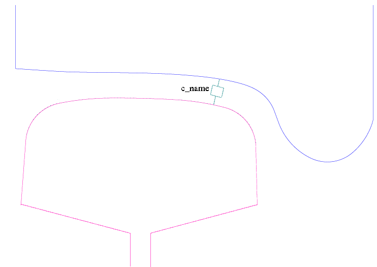
The calculation of creep forces in the contact patch is carried out by interpolation in a four-dimensional lookup-table, which has been calculated according to Kalker's simplified theory of contact.
Before this coupling can be created the variables describing the track irregularities tral111r.y, tral111r.z, tral111r.vy and tral111r.vz must be defined. These variables can for example be created by function func tral_interp_spline.
coupl creep_fasim_1  c_name
            `body1' +-`a1 +-`b1 +-`h1
            `body2' +-`a2 +-`b2 +-`h2
             esys dire
             tral111r.y         # Lateral position track irregularity
             tral111r.z         # Vertical position track irregularity
             tral111r.vy        # Lateral velocity track irregularity
             tral111r.vz        # Vertical velocity track irregularity
             mulfact_nux        # Longitudinal creep relaxation due to contaminated surfaces
             mulfact_nuy        # Lateral      creep relaxation due to contaminated surfaces
             mulfact_spin       # Spin         creep relaxation due to contaminated surfaces
             zfn                # Wheel lift geometric function
             drfn               # Wheel radius geometric function
             gamfn              # Contact angle geometric function
             rofn               # Lateral curvature geometric function
             poswfn             # Lateral position of contact patch on wheel
             posrfn             # Lateral position of contact patch on rail
             knwr.F0_           # Wheel/rail prestess force in normal direction
             knwr_              # Wheel/rail stiffness in normal direction of contact surface
             cnwr_              # Wheel/rail damping   in normal direction of contact surface
             G                  # Combined modulus of rigidity for body1 and body2
             mu                 # Friction coefficient in contact patch
             ro                 # Wheel rolling radius, will vary for OOR-wheels
             nu                 # Combined Poisson's ratio for body1 and body2
             mgitr              # Size of gitter in longitudinal direction
             ngitr              # Size of gitter in lateral direction
             rro                # Longitudinal curvature of rail
| c_name | = | Name of the coupling created. |
| body1 | = | Name of body no. 1, which the coupling is connected to. |
| a1,b1,h1 | = | The coupling's attachment coordinate in body 1, expressed in body 1's local coordinate system lsys. |
| body2 | = | Name of body no. 2 to which the coupling connects. |
| a2,b2,h2 | = | The coupling's attachment coordinate in body 2, expressed in body 2's local coordinate system lsys. |
| esys | = | The coordinate system in which the coupling force will be calculated. |
| dire | = | Working direction for the coupling end connected to body1. The only valid direction for coupling creep_fasim_1 is 'm'. |
| tral111r.y | = | Lateral irregularity to be applied between body1 and body2 |
| tral111r.z | = | Vertical irregularity to be applied between body1 and body2 |
| tral111r.vy | = | Speed of the lateral irregularity between body1 and body2 |
| tral111r.vz | = | Speed of the vertical irregularity between body1 and body2 |
| mulfact_nux | = | Creep reduction factor due to contamination and asperities in the contact surface. mulfact_nux only affects longitudinal creep. |
| mulfact_nuy | = | Creep reduction factor due to contamination and asperities in the contact surface. mulfact_nuy only affects lateral creep. |
| mulfact_spin | = | Creep reduction factor due to contamination and asperities in the contact surface. mulfact_spin only affects spin creep. |
| zfn drfn gamfn rofn poswfn posrfn | = | Wheel/rail geometrical functions generated in the preprocessor kpf. |
| knwr.F0_ | = | Prestress force normal to the contact patch. |
| knwr_ | = | Stiffness normal to the contact surface. Knwr_ must be defined as a memory field where the stiffness is a function of the contact angle. Variable knwr_ can be created in function func intpl_r. |
| cnwr_ | = | Damping normal to the contact surface. Cnwr_ must be defined as a memory field where the stiffness is a function of the contact angle. Variable cnwr_ can be created in function func intpl_r. |
| G | = | Combined modulus of rigidity for body1 and body2 (E/2/(1+nu)) |
| mu | = | Friction coefficient in contact patch. |
| ro | = | Wheel rolling radius. |
| nu | = | Combined Poisson's ratio for body1 and body2 |
| mgitr | = | Size of gitter in longitudinal direction |
| ngitr | = | Size of gitter in lateral direction |
| rro | = | Longitudinal curvature of rail |
Variables generated in the main memory:
Input variables:
| c_name.a1 | = | Attachment coordinate in x-direction on body 1. | ||||||
| c_name.b1 | = | Attachment coordinate in y-direction on body 1. | ||||||
| c_name.h1 | = | Attachment coordinate in z-direction on body 1. | ||||||
| c_name.a2 | = | Attachment coordinate in x-direction on body 2. | ||||||
| c_name.b2 | = | Attachment coordinate in y-direction on body 2. | ||||||
| c_name.h2 | = | Attachment coordinate in z-direction on body 2. | ||||||
| c_name.a | = | Size of contact surface semi-axis in longitudinal direction. | ||||||
| c_name.b | = | Size of contact surface semi-axis in lateral direction. | ||||||
| c_name.a_b | = | The a/b-ratio of the contact ellipse. The semi-axle a is oriented in the longitudinal direction, and the semi-axle b is oriented in the lateral direction. If a/b = 1, the contact patch is circular. | ||||||
| c_name.c | = | The geometrical average radii of the contact ellipse, c is calculated according to:
c= √ a · b where:
|
||||||
| c_name.nux | = | Longitudinal creepage in plane with the contact surface. Positive value gives positive force on the track at the contact patch surface level. | ||||||
| c_name.Fn | = | Contact force perpendicular to the contact surface. | ||||||
| c_name.Fnx | = | Longitudinal creep force in plane with the contact surface. Positive value gives positive force on the track at the contact patch surface level. | ||||||
| c_name.Fny | = | Lateral creep force in plane with the contact surface. Positive value gives positive force on the track at the contact patch surface level. | ||||||
| c_name.Mspin | = | Spin moment in contact patch. | ||||||
| c_name.fwk | = | Energy dissipation in contact patch. |
Generated variables containing forces and moment, acting on body1 and body2:
| c_name.F1x | = | Longitudinal force acting on body1. |
| c_name.F1y | = | Lateral force acting on body1. |
| c_name.F1z | = | Vertical force acting on body1. |
| c_name.M1f | = | Roll moment acting on body1. |
| c_name.M1k | = | Pitch moment acting on body1. |
| c_name.M1p | = | Yaw moment acting on body1. |
| c_name.F2x | = | Longitudinal force acting on body2. |
| c_name.F2y | = | Lateral force acting on body2. |
| c_name.F2z | = | Vertical force acting on body2. |
| c_name.M2f | = | Roll moment acting on body2. |
| c_name.M2k | = | Pitch moment acting on body2. |
| c_name.M2p | = | Yaw moment acting on body2. |
See also:
func wr_coupl_pr3:Here coupl creep_fasim_1 is used in a so called big-function. It's a convenience function that creates the following:
c_type = `creep_fasim_2`
Defines a rolling contact between two masses similar to creep_fasim_1.
In addition to creep_fasim_1 coupl creep_fasim_2 modifies the creepages according to:
"Creep force modelling for rail traction vehicles based on the Fastsim algorithm";
Maksym Spiryagin , Oldrich Polach & Colin Cole;
Vehicle System Dynamics 13 Aug 2013.
The Kalker reduction factor \(k\) is calculated according to the following formula:
\( ~k= k_0\left(\alpha_{inf} + \frac{1-\alpha_{inf}}{1+\beta\cdot\varepsilon}\right) ~ \)
Where:k0 = Input data argument k0 αinf= Input data argument Ainf β = Input data argument beta
\( ~\varepsilon= \frac{1}{4} \cdot \frac{G \pi a b k_0 c_{11}}{Q \mu} \cdot \nu ~~~~~~~~~~~~~~~~ \)
 G = Shear modulus
 a = Contact ellipse longitudinal semi-axis
 b = Contact ellipse lateral semi-axis
 c11= Creepage coefficient in longitudinal direction, Kalker's linear theory
 ν = Total creep
 Q = Wheel load
 μ = Friction coefficient
Before this coupling can be created the variables describing the track irregularities tral111r.y, tral111r.z, tral111r.vy and tral111r.vz must be defined. These variables can for example be created by function func tral_interp_spline.
coupl creep_fasim_2  c_name
            `body1' +-`a1 +-`b1 +-`h1
            `body2' +-`a2 +-`b2 +-`h2
             esys dire
             tral111r.y         # Lateral position track irregularity
             tral111r.z         # Vertical position track irregularity
             tral111r.vy        # Lateral velocity track irregularity
             tral111r.vz        # Vertical velocity track irregularity
             mulfact_nux        # Longitudinal creep relaxation due to contaminated surfaces
             mulfact_nuy        # Lateral      creep relaxation due to contaminated surfaces
             mulfact_spin       # Spin         creep relaxation due to contaminated surfaces
             zfn                # Wheel lift geometric function
             drfn               # Wheel radius geometric function
             gamfn              # Contact angle geometric function
             rofn               # Lateral curvature geometric function
             poswfn             # Lateral position of contact patch on wheel
             posrfn             # Lateral position of contact patch on rail
             knwr.F0_           # Wheel/rail prestess force in normal direction
             knwr_              # Wheel/rail stiffness in normal direction of contact surface
             cnwr_              # Wheel/rail damping   in normal direction of contact surface
             G                  # Combined modulus of rigidity for body1 and body2
             mu                 # Friction coefficient in contact patch
             ro                 # Wheel rolling radius, will vary for OOR-wheels
             poisson            # Combined Poisson's ratio for body1 and body2
             mgitr              # Size of gitter in longitudinal direction
             ngitr              # Size of gitter in lateral direction
             rro                # Longitudinal curvature of rail
             k0                 # Initial value of Kalker's reduction factor
             Ainf               # Fraction of "k0" at creep values approaching infinity
             beta               # Non-dimensional parameter related to the decrease of the contact stiffness
| c_name | = | Name of the coupling created. |
| body1 | = | Name of body no. 1, which the coupling is connected to. |
| a1,b1,h1 | = | The coupling's attachment coordinate in body 1, expressed in body 1's local coordinate system lsys. |
| body2 | = | Name of body no. 2 to which the coupling connects. |
| a2,b2,h2 | = | The coupling's attachment coordinate in body 2, expressed in body 2's local coordinate system lsys. |
| esys | = | The coordinate system in which the coupling force will be calculated. |
| dire | = | Working direction for the coupling end connected to body1. The only valid direction for coupling creep_fasim_2 is 'm'. |
| tral111r.y | = | Lateral irregularity to be applied between body1 and body2 |
| tral111r.z | = | Vertical irregularity to be applied between body1 and body2 |
| tral111r.vy | = | Speed of the lateral irregularity between body1 and body2 |
| tral111r.vz | = | Speed of the vertical irregularity between body1 and body2 |
| mulfact_nux | = | Creep reduction factor due to contamination and asperities in the contact surface. mulfact_nux only affects longitudinal creep. |
| mulfact_nuy | = | Creep reduction factor due to contamination and asperities in the contact surface. mulfact_nuy only affects lateral creep. |
| mulfact_spin | = | Creep reduction factor due to contamination and asperities in the contact surface. mulfact_spin only affects spin creep. |
| zfn drfn gamfn rofn poswfn posrfn | = | Wheel/rail geometrical functions generated in the preprocessor kpf. |
| knwr.F0_ | = | Prestress force normal to the contact patch. |
| knwr_ | = | Stiffness normal to the contact surface. Knwr_ must be defined as a memory field where the stiffness is a function of the contact angle. Variable knwr_ can be created in function func intpl_r. |
| cnwr_ | = | Damping normal to the contact surface. Cnwr_ must be defined as a memory field where the stiffness is a function of the contact angle. Variable cnwr_ can be created in function func intpl_r. |
| G | = | Combined modulus of rigidity for body1 and body2 |
| mu | = | Friction coefficient in contact patch. |
| ro | = | Longitudinal curve radius of wheel in contact patch. |
| poisson | = | Combined Poisson's ratio for body1 and body2 (for steel ~0.3) |
| mgitr | = | Size of gitter in longitudinal direction |
| ngitr | = | Size of gitter in lateral direction |
| rro | = | Longitudinal curvature of rail |
| k0 | = | Initial value of Kalker's reduction factor at creep values close to zero, 0 < k0 <= 1 |
| Ainf | = | Fraction of "k0" at creep values approaching infinity, 0 <= ainf <= 1 |
| beta | = | The non-dimensional parameter related to the decrease of the contact stiffness with the increase of the slip area size, 0 <= beta |
Variables generated in the main memory:
Input variables:
| c_name.a1 | = | Attachment coordinate in x-direction on body 1. | ||||||
| c_name.b1 | = | Attachment coordinate in y-direction on body 1. | ||||||
| c_name.h1 | = | Attachment coordinate in z-direction on body 1. | ||||||
| c_name.a2 | = | Attachment coordinate in x-direction on body 2. | ||||||
| c_name.b2 | = | Attachment coordinate in y-direction on body 2. | ||||||
| c_name.h2 | = | Attachment coordinate in z-direction on body 2. | ||||||
| c_name.ro_cur | = | Current wheel radius. | ||||||
| c_name.ro_init | = | Initial wheel radius. | ||||||
| c_name.rro | = | Longitudinal curvature of rail. To be set especially when running on roller rigs. | ||||||
| c_name.a | = | Size of contact surface semi-axis in longitudinal direction. | ||||||
| c_name.b | = | Size of contact surface semi-axis in lateral direction. | ||||||
| c_name.a_b | = | The a/b-ratio of the contact ellipse. The semi-axle a is oriented in the longitudinal direction, and the semi-axle b is oriented in the lateral direction. If a/b = 1, the contact patch is circular. | ||||||
| c_name.c | = | The geometrical average radii of the contact ellipse, c is calculated according to:
\( ~ c= \sqrt{a \cdot b } ~ \) where:
|
||||||
| c_name.ga | = | Combined modulus of rigidity for body1 and body2. | ||||||
| c_name.si | = | Combined Poisson's ratio for body1 and body2. | ||||||
| c_name.mu | = | Friction coefficient in contact patch. | ||||||
| c_name.k0 | = | Initial value of Kalker's reduction factor. | ||||||
| c_name.Ainf | = | Fraction of "k0" at creep values approaching infinity. | ||||||
| c_name.beta | = | The non-dimensional parameter related to the decrease of the contact stiffness with the increase of the slip area size. | ||||||
| c_name.Fknwrz | = | Force in stiffness knwr. | ||||||
| c_name.Fcnwrz | = | Force in damper cnwr. | ||||||
| c_name.vux | = | Longitudinal speed difference in contact patch according to lsys coordinate system. | ||||||
| c_name.vuy | = | Lateral speed difference in contact patch according to lsys coordinate system. | ||||||
| c_name.vuz | = | Vertical speed difference in contact patch according to lsys coordinate system. | ||||||
| c_name.Vref | = | Reference speed when evaluating the creepages. | ||||||
| c_name.nux | = | Longitudinal creepage in plane with the contact patch. | ||||||
| c_name.nuy | = | Lateral creepage in plane with the contact patch. | ||||||
| c_name.spin | = | Spin creepage in plane with the contact patch. | ||||||
| c_name.mgitr | = | Size of mesh in longitudinal direction. | ||||||
| c_name.ngitr | = | Size of mesh in lateral direction. | ||||||
| c_name.Fn | = | Contact force perpendicular to the contact patch. | ||||||
| c_name.Fnx | = | Longitudinal creep force in plane with the contact patch. Positive value gives positive force on the track at the contact patch surface level. | ||||||
| c_name.Fny | = | Lateral creep force in plane with the contact patch. Positive value gives positive force on the track at the contact patch surface level. | ||||||
| c_name.Mspin | = | Spin moment in contact patch. | ||||||
| c_name.fwk | = | Energy dissipation in contact patch. |
Generated variables containing forces and moment, acting on body1 and body2:
| c_name.F1x | = | Longitudinal force acting on body1. |
| c_name.F1y | = | Lateral force acting on body1. |
| c_name.F1z | = | Vertical force acting on body1. |
| c_name.M1f | = | Roll moment acting on body1. |
| c_name.M1k | = | Pitch moment acting on body1. |
| c_name.M1p | = | Yaw moment acting on body1. |
| c_name.F2x | = | Longitudinal force acting on body2. |
| c_name.F2y | = | Lateral force acting on body2. |
| c_name.F2z | = | Vertical force acting on body2. |
| c_name.M2f | = | Roll moment acting on body2. |
| c_name.M2k | = | Pitch moment acting on body2. |
| c_name.M2p | = | Yaw moment acting on body2. |
c_type = `creep_fasim_4`
Defines a rolling contact between two masses.
Similar to creep_fasim_1, but this wheel/rail-coupling uses the wheel and rail profiles directly.
I.e. it is not necessary to create wheel/rail-geometry functions in pre-processor KPF.
Before this coupling can be created the variables describing the track irregularities tral111r.y, tral111r.z, tral111r.vy and tral111r.vz must be defined. These variables can for example be created by function func tral_interp_spline.
coupl creep_fasim_4  c_name
            `body1' +-`a1 +-`b1 +-`h1
            `body2' +-`a2 +-`b2 +-`h2
             esys dire
             tral111r.y         # Lateral position track irregularity
             tral111r.z         # Vertical position track irregularity
             tral111r.vy        # Lateral velocity track irregularity
             tral111r.vz        # Vertical velocity track irregularity
             ro                 # Nominal rolling radius of wheel
             iorient            # Orientation +1= Left side; -1= Right side
             shape_long         # Shape of the contact pressure distribution in longitudinal direction
             mulfact_nux        # Longitudinal creep relaxation due to contaminated surfaces
             mulfact_nuy        # Lateral      creep relaxation due to contaminated surfaces
             mulfact_spin       # Spin         creep relaxation due to contaminated surfaces
#
             wheel_prof         # Wheel profile
             75                 # Only here for backward compatibility reasons
             mgitr ngitr        # Size of contact mesh in long & lat direction
             rail_prof_mem      # Rail profile memory field
             3                  # Only here for backward compatibility reasons
#
             Gc                 # Combined Shear Modulus
             nuc                # Combined Poisson's ratio
#
             rro                # Vertical curvature rail
             knwr               # Stiffness normal to contact patch
             cnwr               # Damping   normal to contact patch
             penmax             # No force if the penetration is deeper than penmax
             dy                 # Interpolate in equidistant steps in rail profile
#
             mu1                # Friction coefficient in wheel/rail contact cp1
             mu2                # Friction coefficient in wheel/rail contact cp2
             mu3                # Friction coefficient in wheel/rail contact cp3
             mu4                # Friction coefficient in wheel/rail contact cp4
             mu5                # Friction coefficient in wheel/rail contact cp5
             mu6                # Friction coefficient in wheel/rail contact cp6
             mu7                # Friction coefficient in wheel/rail contact cp7
             mu8                # Friction coefficient in wheel/rail contact cp8
             mu9                # Friction coefficient in wheel/rail contact cp9
             mu0                # Friction coefficient in wheel/rail contact cp0
| c_name | = | Name of the coupling created. |
| body1 | = | Name of body no. 1, which the coupling is connected to. |
| a1,b1,h1 | = | The coupling's attachment coordinate in body 1, expressed in body 1's local coordinate system lsys. |
| body2 | = | Name of body no. 2 to which the coupling connects. |
| a2,b2,h2 | = | The coupling's attachment coordinate in body 2, expressed in body 2's local coordinate system lsys. |
| esys | = | The coordinate system in which the coupling force will be calculated. |
| dire | = | Working direction for the coupling end connected to body1. The only valid direction for coupling creep_fasim_4 is 'm'. |
| tral111r.y | = | Lateral irregularity to be applied between body1 and body2 |
| tral111r.z | = | Vertical irregularity to be applied between body1 and body2 |
| tral111r.vy | = | Speed of the lateral irregularity between body1 and body2 |
| tral111r.vz | = | Speed of the vertical irregularity between body1 and body2 |
| ro | = | Nominal rolling radius of wheel. For OOR-wheels the value of this variable will vary with the pitch angle of the wheelset. |
| iorient | = | Orientation of the wheel and rail profiles. Wheel profile files and rail profile files are always describing wheels and a rails for the left side of the vehicle. Therefore this argument shall be set equal to "+1" if this wheel/rail-coupling is on the left side of the vehicle, and equal to "-1" for the right side of the vehicle. |
| shape_long | = | Shape of the contact pressure distribution in longitudinal direction: 1= Circular; 2= Parabolic |
| mulfact_nux | = | Creep reduction factor due to contamination and asperities in the contact surface. mulfact_nux only affects longitudinal creep. |
| mulfact_nuy | = | Creep reduction factor due to contamination and asperities in the contact surface. mulfact_nuy only affects lateral creep. |
| mulfact_spin | = | Creep reduction factor due to contamination and asperities in the contact surface. mulfact_spin only affects spin creep. |
| wheel_prof | = | Memory field describing the wheel profile, e.g. func intpl_r |
| mgitr | = | Size of gitter in longitudinal direction |
| ngitr | = | Size of gitter in lateral direction |
| rail_prof_mem | = | Two dimensional memory field describing the rail profile along the track. Can be described in e.g. func intpl2_r |
| Gc | = | Combined modulus of rigidity for body1 and body2 (E/2/(1+nu)) |
| nuc | = | Combined Poisson's ratio for body1 and body2 |
| rro | = | Longitudinal curvature of rail or radius of rollers in a roller rig |
| knwr | = | Stiffness normal to the contact surface. If knwr is a memory field, the value of the contact stiffness will depend on the contact patch angle. |
| cnwr | = | Damping normal to the contact surface. If cnwr is a memory field, the value of the damping coefficient will depend on the contact patch angle. |
| penmax | = | The contact force is based on the contact stiffness "knwr" and the penetration between wheel and rail, If the penetration is deeper than "penmax" the wheel surface is considered to be on the other side of the rail surface, hence no contact force. |
| dy | = | It is not necessary that the rail and wheel profile has equidistant steps in lateral direction. Coupl creep_fasim_4 will take care of this and interpolate in equidistant steps "dy" over the profiles. |
| mu1 | = | Friction coefficient in contact patch cp1. |
| mu2 | = | Friction coefficient in contact patch cp2. |
| mu3 | = | Friction coefficient in contact patch cp3. |
| mu4 | = | Friction coefficient in contact patch cp4. |
| mu5 | = | Friction coefficient in contact patch cp5. |
| mu6 | = | Friction coefficient in contact patch cp6. |
| mu7 | = | Friction coefficient in contact patch cp7. |
| mu8 | = | Friction coefficient in contact patch cp8. |
| mu9 | = | Friction coefficient in contact patch cp9. |
| mu0 | = | Friction coefficient in contact patch cp0. |
Variables generated in the main memory:
Input variables:
| c_name.a1 | = | Attachment coordinate in x-direction on body 1. | ||||||
| c_name.b1 | = | Attachment coordinate in y-direction on body 1. | ||||||
| c_name.h1 | = | Attachment coordinate in z-direction on body 1. | ||||||
| c_name.a2 | = | Attachment coordinate in x-direction on body 2. | ||||||
| c_name.b2 | = | Attachment coordinate in y-direction on body 2. | ||||||
| c_name.h2 | = | Attachment coordinate in z-direction on body 2. | ||||||
| c_name.a | = | Size of contact surface semi-axis in longitudinal direction. | ||||||
| c_name.b | = | Size of contact surface semi-axis in lateral direction. | ||||||
| c_name.a_b | = | The a/b-ratio of the contact ellipse. The semi-axle a is oriented in the longitudinal direction, and the semi-axle b is oriented in the lateral direction. If a/b = 1, the contact patch is circular. | ||||||
| c_name.c | = | The geometrical average radii of the contact ellipse, c is calculated according to:
c= √ a · b where:
|
||||||
| c_name.nux | = | Longitudinal creepage in plane with the contact surface. Positive value gives positive force on the track at the contact patch surface level. | ||||||
| c_name.Fn | = | Contact force perpendicular to the contact surface. | ||||||
| c_name.Fnx | = | Longitudinal creep force in plane with the contact surface. Positive value gives positive force on the track at the contact patch surface level. | ||||||
| c_name.Fny | = | Lateral creep force in plane with the contact surface. Positive value gives positive force on the track at the contact patch surface level. | ||||||
| c_name.Mspin | = | Spin moment in contact patch. | ||||||
| c_name.fwk | = | Energy dissipation in contact patch. |
Generated variables containing forces and moment, acting on body1 and body2:
| c_name.F1x | = | Longitudinal force acting on body1. |
| c_name.F1y | = | Lateral force acting on body1. |
| c_name.F1z | = | Vertical force acting on body1. |
| c_name.M1f | = | Roll moment acting on body1. |
| c_name.M1k | = | Pitch moment acting on body1. |
| c_name.M1p | = | Yaw moment acting on body1. |
| c_name.F2x | = | Longitudinal force acting on body2. |
| c_name.F2y | = | Lateral force acting on body2. |
| c_name.F2z | = | Vertical force acting on body2. |
| c_name.M2f | = | Roll moment acting on body2. |
| c_name.M2k | = | Pitch moment acting on body2. |
| c_name.M2p | = | Yaw moment acting on body2. |
c_type = `creep_fastrip_1`
Defines a rolling contact between two masses.
The contact forces between the two bodies are calculated in ANALYN and FaStrip, developed by PhD Matin Shahzamanian Sichani KTH Stockholm,
TRITA-AVE 2016:02, ISSN 1651-7660, ISBN 978-91-7595-846-0.
In coupling creep_fastrip_1 the profile of the rail and wheel are used directly.
Therefore it is not necessary to create wheel/rail geometry functions in program KPF.
Gensys detects all possible contact patches between the wheel and rail profiles.
In the center of each possible contact patch a contact coordinate system is created,
with its X-axis pointing forward along the track and its Z-axis normal to the contact patch pointing towards the rail.
For each contact patch a mesh is created, containing the perpendicular distances between wheel and rail.
A positive distance indicates a gap between wheel and rail.
A negative distance indicates that the undeformed profiles has penetrated each other.
Up to 9 contact patches can be in contact simultaneously.
N.B.
Integration methods that do backsteps are not possible to use together with coupling creep_fastrip_1.
Recommended integrator with coupling creep_fastrip_1 is runge_kutta with a fixed time step.
Before this coupling can be created the variables describing the track irregularities tral111r.y, tral111r.z, tral111r.vy and tral111r.vz must be defined. These variables can for example be created in function func tral_interp_spline.
 coupl creep_fastrip_1  c_name
              `body1' +-`a1 +-`b1 +-`h1
              `body2' +-`a2 +-`b2 +-`h2
               esys dire           # Euler system and direction of action
            +-`tral.y              # Lateral position track irregularity
            +-`tral.z              # Vertical position track irregularity
            +-`tral.vy             # Lateral velocity track irregularity
            +-`tral.vz             # Vertical velocity track irregularity
            +-`ro                  # Wheel rolling radius, will vary for OOR-wheels
               iorient             # Orientation of profiles +1=left, -1=right
            +-`ixshape             # Shape in long direction
            +-`mulfact_nux         # Longitudinal creep relaxation due to contaminated surfaces
            +-`mulfact_nuy         # Lateral      creep relaxation due to contaminated surfaces
            +-`mulfact_spin        # Spin         creep relaxation due to contaminated surfaces

               wheel_prof          # Wheel profile defined via a memory field, e.g. func intpl_r
            +-`dx                  # Longitudinal distance between nodes in each contact patch mesh
            +-`dy                  # Lateral distance between nodes in each contact patch mesh
               rail_prof_memfield  # Rail profiles defined via a memory field, e.g. func intpl2_r

            +-`G_comb              # Combined Shear Modulus
            +-`nu_comb             # Combined Poisson's ratio

                                   # Wear according to Achard's law
            +-`HV                  # Hardness in Vickers N/m2
            +-`kp1                 # Contact pressure level, border 1
            +-`kv1                 # Sliding speed, border 1
            +-`kv2                 # Sliding speed, border 2
            +-`k1                  # Wear rates in the different
            +-`k2                  # areas of the
            +-`k3                  # Archard's wear chart
            +-`k4                  # See figure below

            +-`ror                 # Vertical curvature rail head

            +-`mu_1                # Friction coefficient, contact patch #1
            +-`mu_2                # Friction coefficient, contact patch #2
            +-`mu_3                # Friction coefficient, contact patch #3
            +-`mu_4                # Friction coefficient, contact patch #4
            +-`mu_5                # Friction coefficient, contact patch #5
            +-`mu_6                # Friction coefficient, contact patch #6
            +-`mu_7                # Friction coefficient, contact patch #7
            +-`mu_8                # Friction coefficient, contact patch #8
            +-`mu_9                # Friction coefficient, contact patch #9
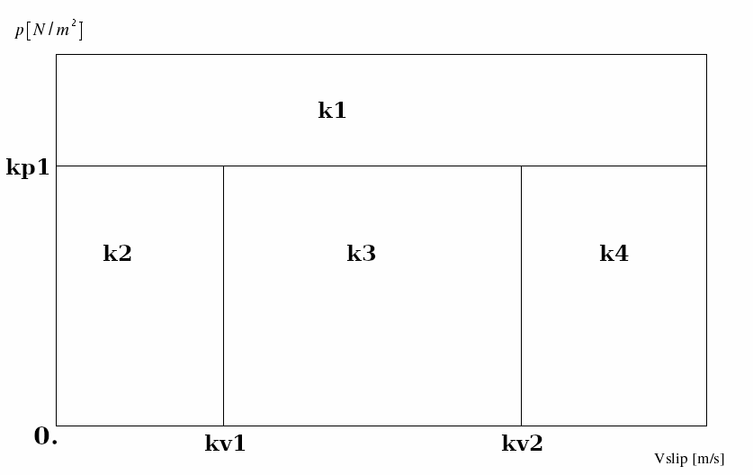
| c_name | = | Name of the coupling created. N.B. the name must start with the letters "cp_" |
| body1 | = | Name of body no. 1, which the coupling is connected to. |
| a1,b1,h1 | = | The coupling's attachment coordinate in body 1, expressed in body 1's local coordinate system lsys. |
| body2 | = | Name of body no. 2 to which the coupling connects. |
| a2,b2,h2 | = | The coupling's attachment coordinate in body 2, expressed in body 2's local coordinate system lsys. |
| esys | = | The coordinate system in which the coupling force will be calculated. |
| dire | = | Working direction for the coupling end connected to body1. The only valid direction for coupling creep_fastrip_1 is 'm'. |
| tral.y | = | Lateral irregularity to be applied between wheel and rail |
| tral.z | = | Vertical irregularity to be applied between wheel and rail |
| tral.vy | = | Speed of lateral irregularity between wheel and rail |
| tral.vz | = | Speed of vertical irregularity between wheel and rail |
| ro | = | Nominal wheel rolling radius. |
| iorient | = | Orientation of wheel and rail profile. Normally wheel- and rail- profiles are measured from outside of track towards track center line, which makes both profiles to look as left handed profiles. The user can with this input data mirror the profiles on the right side of the track, without generate special right handed profiles. |
| ixshape | = | =1 => Circular shape, longitudinal curvature according to cp#_c_name(3:).irx =2 => Parabolic shape, approximately longitudinal curvature according to cp#_c_name(3:).irx |
| mulfact_nux | = | Creep reduction factor due to contamination and asperities in the contact surface. mulfact_nux only affects longitudinal creep. |
| mulfact_nuy | = | Creep reduction factor due to contamination and asperities in the contact surface. mulfact_nuy only affects lateral creep. |
| mulfact_spin | = | Creep reduction factor due to contamination and asperities in the contact surface. mulfact_spin only affects spin creep. |
Variables generated in the main memory:
Input variables:
| c_name.a1 | = | Attachment coordinate in x-direction on body 1. |
| c_name.b1 | = | Attachment coordinate in y-direction on body 1. |
| c_name.h1 | = | Attachment coordinate in z-direction on body 1. |
| c_name.a2 | = | Attachment coordinate in x-direction on body 2. |
| c_name.b2 | = | Attachment coordinate in y-direction on body 2. |
| c_name.h2 | = | Attachment coordinate in z-direction on body 2. |
| c_name.dx | = | Longitudinal distance between nodes in each contact patch mesh. |
| c_name.dy | = | Lateral distance between nodes in each contact patch mesh. |
Output variables:
| c_name.eta | = | Relative lateral motion between wheel and rail. |
| c_name.veta | = | Relative lateral speed difference between wheel and rail. |
Variables created for each contact mesh:
| cp#_c_name(3:).dr | = | Contact patch effective wheel radius. |
| cp#_c_name(3:).gam | = | Contact patch effective roll(X-rot) angle. |
| cp#_c_name(3:).irx | = | Contact patch effective wheel longitudinal curvature. |
| cp#_c_name(3:).ksi | = | Contact patch longitudinal position due to roll and yaw angle. |
| cp#_c_name(3:).posw | = | Contact patch effective lateral position on wheel, lateral direction. |
| cp#_c_name(3:).posr | = | Contact patch effective lateral position on rail, lateral direction. |
| cp#_c_name(3:).bo | = | Contact patch effective lateral position relative track center line. |
| cp#_c_name(3:).pen | = | Contact patch max undeformed penetration. |
| cp#_c_name(3:).udefa | = | Longitudinal semi-length of potential contact area. I.e. the length of the actual contact patch can be up to 2*cp#_c_name(3:).udefa. |
| cp#_c_name(3:).udefb | = | Lateral semi-width of potential contact area. I.e. the width of the actual contact patch can be up to 2*cp#_c_name(3:).udefb. |
| cp#_c_name(3:).area | = | Actual contact area. |
| cp#_c_name(3:).slip_area | = | Relative size of slip zone (slip_area/tot_area). |
| cp#_c_name(3:).vux | = | Contact patch effective longitudinal difference speed. |
| cp#_c_name(3:).vuy | = | Contact patch effective lateral difference speed. |
| cp#_c_name(3:).vuz | = | Contact patch effective vertical difference speed. |
| cp#_c_name(3:).Vref | = | Contact patch effective reference speed. |
| cp#_c_name(3:).nux | = | Contact patch effective longitudinal creepage. |
| cp#_c_name(3:).nuy | = | Contact patch effective lateral creepage. |
| cp#_c_name(3:).spin | = | Contact patch effective spin creepage. |
| cp#_c_name(3:).Fn | = | Contact patch contact force. |
| cp#_c_name(3:).Fny | = | Contact patch lateral creep force tangential to contact surface (angle cp#_c_name(3:).gam). |
| cp#_c_name(3:).Fx | = | Contact patch longitudinal force. |
| cp#_c_name(3:).Fy | = | Contact patch lateral force (along Y-axis of lsa) |
| cp#_c_name(3:).Fz | = | Contact patch vertical force (along Z-axis of lsa) |
| cp#_c_name(3:).Mspin | = | Contact patch spin torque tangential to contact surface (angle cp#_c_name(3:).gam). |
Where: # = The number of the contact patch
Forces and torques acting on adjacent bodies:
| c_name.F1x | = | Longitudinal force acting on body1. |
| c_name.F1y | = | Lateral force acting on body1. |
| c_name.F1z | = | Vertical force acting on body1. |
| c_name.M1f | = | Roll torque acting on body1. |
| c_name.M1k | = | Pitch torque acting on body1. |
| c_name.M1p | = | Yaw torque acting on body1. |
| c_name.F2x | = | Longitudinal force acting on body2. |
| c_name.F2y | = | Lateral force acting on body2. |
| c_name.F2z | = | Vertical force acting on body2. |
| c_name.M2f | = | Roll torque acting on body2. |
| c_name.M2k | = | Pitch torque acting on body2. |
| c_name.M2p | = | Yaw torque acting on body2. |
c_type = `creep_fastrip_3`
Defines a rolling contact between two masses.
The contact forces between the two bodies are calculated in a linear spring normal to the contact surface and FaStrip.
Routine FaStrip has been developed by PhD Matin Shahzamanian Sichani KTH Stockholm,
TRITA-AVE 2016:02, ISSN 1651-7660, ISBN 978-91-7595-846-0.
In order to speed up the simulation times wheel/rail-geometry functions generated by program KPF are used.
Before this coupling can be created the variables describing the track irregularities tral111r.y, tral111r.z, tral111r.vy and tral111r.vz must be defined. These variables can for example be created in function func tral_interp_spline.
 coupl creep_fastrip_3  c_name
              `body1' +-`a1 +-`b1 +-`h1
              `body2' +-`a2 +-`b2 +-`h2
               esys dire           # Euler system and direction of action
            +-`tral.y              # Lateral position track irregularity
            +-`tral.z              # Vertical position track irregularity
            +-`tral.vy             # Lateral velocity track irregularity
            +-`tral.vz             # Vertical velocity track irregularity
            +-`mulfact_nux         # Longitudinal creep relaxation due to contaminated surfaces
            +-`mulfact_nuy         # Lateral      creep relaxation due to contaminated surfaces
            +-`mulfact_spin        # Spin         creep relaxation due to contaminated surfaces

             zfn                # Wheel lift geometric function
             drfn               # Wheel radius geometric function
             gamfn              # Contact angle geometric function
             rofn               # Lateral curvature geometric function
             poswfn             # Lateral position of contact patch on wheel
             posrfn             # Lateral position of contact patch on rail

             +-`knwr.F0_           # Wheel/rail prestess force in normal direction
             +-`knwr_              # Wheel/rail stiffness in normal direction of contact surface
             +-`cnwr_              # Wheel/rail damping   in normal direction of contact surface

             +-`G_comb             # Combined Shear Modulus

             +-`mu                 # Friction coefficient in contact patch
             +-`ro                 # Wheel rolling radius, will vary for OOR-wheels
             +-`nu_comb            # Combined Poisson's ratio for body1 and body2
             +-`mgitr              # Size of gitter in longitudinal direction
             +-`ngitr              # Size of gitter in lateral direction
             +-`rro                # Longitudinal curvature of rail
| c_name | = | Name of the coupling created. N.B. the name must start with the letters "cp_" |
| body1 | = | Name of body no. 1, which the coupling is connected to. |
| a1,b1,h1 | = | The coupling's attachment coordinate in body 1, expressed in body 1's local coordinate system lsys. |
| body2 | = | Name of body no. 2 to which the coupling connects. |
| a2,b2,h2 | = | The coupling's attachment coordinate in body 2, expressed in body 2's local coordinate system lsys. |
| esys | = | The coordinate system in which the coupling force will be calculated. |
| dire | = | Working direction for the coupling end connected to body1. The only valid direction for coupling creep_fastrip_3 is 'm'. |
| tral.y | = | Lateral irregularity to be applied between wheel and rail |
| tral.z | = | Vertical irregularity to be applied between wheel and rail |
| tral.vy | = | Speed of lateral irregularity between wheel and rail |
| tral.vz | = | Speed of vertical irregularity between wheel and rail |
| ro | = | Nominal wheel rolling radius. |
| mulfact_nux | = | Creep reduction factor due to contamination and asperities in the contact surface. mulfact_nux only affects longitudinal creep. |
| mulfact_nuy | = | Creep reduction factor due to contamination and asperities in the contact surface. mulfact_nuy only affects lateral creep. |
| mulfact_spin | = | Creep reduction factor due to contamination and asperities in the contact surface. mulfact_spin only affects spin creep. |
Variables generated in the main memory:
Input variables:
| c_name.a1 | = | Attachment coordinate in x-direction on body 1. |
| c_name.b1 | = | Attachment coordinate in y-direction on body 1. |
| c_name.h1 | = | Attachment coordinate in z-direction on body 1. |
| c_name.a2 | = | Attachment coordinate in x-direction on body 2. |
| c_name.b2 | = | Attachment coordinate in y-direction on body 2. |
| c_name.h2 | = | Attachment coordinate in z-direction on body 2. |
| c_name.dx | = | Longitudinal distance between nodes in each contact patch mesh. |
| c_name.dy | = | Lateral distance between nodes in each contact patch mesh. |
Output variables:
| c_name.eta | = | Relative lateral motion between wheel and rail. |
| c_name.veta | = | Relative lateral speed difference between wheel and rail. |
Variables created for each contact mesh:
| c_name.dr | = | Contact patch effective wheel radius. |
| c_name.gam | = | Contact patch effective roll(X-rot) angle. |
| c_name.irx | = | Contact patch effective wheel longitudinal curvature. |
| c_name.ksi | = | Contact patch longitudinal position due to roll and yaw angle. |
| c_name.posw | = | Contact patch effective lateral position on wheel, lateral direction. |
| c_name.posr | = | Contact patch effective lateral position on rail, lateral direction. |
| c_name.bo | = | Contact patch effective lateral position relative track center line. |
| c_name.pen | = | Contact patch max undeformed penetration. |
| c_name.vux | = | Contact patch effective longitudinal difference speed. |
| c_name.vuy | = | Contact patch effective lateral difference speed. |
| c_name.vuz | = | Contact patch effective vertical difference speed. |
| c_name.Vref | = | Contact patch effective reference speed. |
| c_name.nux | = | Contact patch effective longitudinal creepage. |
| c_name.nuy | = | Contact patch effective lateral creepage. |
| c_name.spin | = | Contact patch effective spin creepage. |
| c_name.Fn | = | Contact patch contact force. |
| c_name.Fny | = | Contact patch lateral creep force tangential to contact surface (angle c_name.gam). |
| c_name.Fx | = | Contact patch longitudinal force. |
| c_name.Fy | = | Contact patch lateral force (along Y-axis of lsa) |
| c_name.Fz | = | Contact patch vertical force (along Z-axis of lsa) |
| c_name.Mspin | = | Contact patch spin torque tangential to contact surface (angle c_name.gam). |
Forces and torques acting on adjacent bodies:
| c_name.F1x | = | Longitudinal force acting on body1. |
| c_name.F1y | = | Lateral force acting on body1. |
| c_name.F1z | = | Vertical force acting on body1. |
| c_name.M1f | = | Roll torque acting on body1. |
| c_name.M1k | = | Pitch torque acting on body1. |
| c_name.M1p | = | Yaw torque acting on body1. |
| c_name.F2x | = | Longitudinal force acting on body2. |
| c_name.F2y | = | Lateral force acting on body2. |
| c_name.F2z | = | Vertical force acting on body2. |
| c_name.M2f | = | Roll torque acting on body2. |
| c_name.M2k | = | Pitch torque acting on body2. |
| c_name.M2p | = | Yaw torque acting on body2. |
c_type = `creep_lookuptable_1`
Defines a rolling contact between two masses.
The main purpose of this coupling is to model the normal- and tangential- forces occuring
in the contact patch between wheel and rail.
The advantage of using this coupling instead of the substructure
wr_coupl_pe3.ins
is that the user can
model the wheelset and track more freely.
This coupling can also be used for simulating a guard rail,
or if a vehicle has derailed this couling can be used for modeling the contact
between the wheels and the sleepers.
The creep-forces which arise in the contact patch are calculated from the following parameters: contact pressure, creepage, the surfaces' radii of curvature, coefficient of friction, material constants. The creep forces are interpolated in a four-dimensional matrix, where the input data quantities are creep, creepage direction, spin and the contact ellipse's a/b-ratio By introducing dimensionless parameters for the creepages the four-dimensional matrix can be calculated in advance, and stored in a block data subroutine. The four-dimensional matrix has been calculated according to Kalker's simplified theory.
Before this coupling can be created the variables describing the track irregularities tral111r.y, tral111r.z, tral111r.vy and tral111r.vz must be defined. These variables can for example be created by function func tral_interp_spline.
 coupl creep_lookuptable_1  c_name
              `body1' +-`a1 +-`b1 +-`h1
              `body2' +-`a2 +-`b2 +-`h2
               esys dire
               tral111r.y         # Lateral position track irregularity
               tral111r.z         # Vertical position track irregularity
               tral111r.vy        # Lateral velocity track irregularity
               tral111r.vz        # Vertical velocity track irregularity
               mulfact_nux        # Longitudinal creep relaxation due to contaminated surfaces
               mulfact_nuy        # Lateral      creep relaxation due to contaminated surfaces
               mulfact_spin       # Spin         creep relaxation due to contaminated surfaces
               zfn                # Wheel lift geometric function
               drfn               # Wheel radius geometric function
               gamfn              # Contact angle geometric function
               rofn               # Lateral curvature geometric function
               poswfn             # Lateral position of contact patch on wheel
               posrfn             # Lateral position of contact patch on rail
               knwr.F0_           # Wheel/rail prestess force in normal direction
               knwr_              # Wheel/rail stiffness in normal direction of contact surface
               cnwr_              # Wheel/rail damping   in normal direction of contact surface
               E_modulus          # Combined modulus of elasticity for body1 and body2
               poisson            # Combined Poisson's ratio for body1 and body2
               mu                 # Friction coefficient in contact patch
               ro                 # Wheel rolling radius, will vary for OOR-wheels
               rro                # Vertical radius of rail
| c_name | = | Name of the coupling created. |
| body1 | = | Name of body no. 1, which the coupling is connected to. |
| a1,b1,h1 | = | The coupling's attachment coordinate in body 1, expressed in body 1's local coordinate system lsys. |
| body2 | = | Name of body no. 2 to which the coupling connects. |
| a2,b2,h2 | = | The coupling's attachment coordinate in body 2, expressed in body 2's local coordinate system lsys. |
| esys | = | The coordinate system in which the coupling force will be calculated. |
| dire | = | Working direction for the coupling end connected to body1. The only valid direction for coupling creep_lookuptable_1 is 'm'. |
| tral111r.y | = | Lateral irregularity to be applied between body1 and body2 |
| tral111r.z | = | Vertical irregularity to be applied between body1 and body2 |
| tral111r.vy | = | Speed of the lateral irregularity between body1 and body2 |
| tral111r.vz | = | Speed of the vertical irregularity between body1 and body2 |
| mulfact_nux | = | Creep reduction factor due to contamination and asperities in the contact surface. mulfact_nux only affects longitudinal creep. |
| mulfact_nuy | = | Creep reduction factor due to contamination and asperities in the contact surface. mulfact_nuy only affects lateral creep. |
| mulfact_spin | = | Creep reduction factor due to contamination and asperities in the contact surface. mulfact_spin only affects spin creep. |
| zfn, drfn, gamfn, rofn, poswfn, posrfn | = | Wheel/rail geometrical functions generated by preprocessor kpf. |
| knwr.F0_ | = | Prestress force normal to the contact patch. |
| knwr_ | = | Stiffness normal to the contact surface. |
| cnwr_ | = | Damping normal to the contact surface. |
| E_modulus | = | Combined modulus of elasticity for body1 and body2 (for steel ~2e11) |
| poisson | = | Combined Poisson's ratio for body1 and body2 (for steel ~0.3) |
| mu | = | Friction coefficient in contact patch. |
| ro | = | Longitudinal curve radius in contact patch. |
| rro | = | In this argument the user has the possibility to give a vertical curve radius to the rails. On a normal track this curve radius is very big. If the radius is equal or greater than 1e99, the effect on the size of the contact ellipse is neglected. With this input data argument the user has the possibility to simulate a vehicle standing on rollers in a roller rig. |
Variables generated in the main memory:
Input variables:
| c_name.a1 | = | Attachment coordinate in x-direction on body 1. | ||||||||||||
| c_name.b1 | = | Attachment coordinate in y-direction on body 1. | ||||||||||||
| c_name.h1 | = | Attachment coordinate in z-direction on body 1. | ||||||||||||
| c_name.a2 | = | Attachment coordinate in x-direction on body 2. | ||||||||||||
| c_name.b2 | = | Attachment coordinate in y-direction on body 2. | ||||||||||||
| c_name.h2 | = | Attachment coordinate in z-direction on body 2. | ||||||||||||
| c_name.a_b | = | The a/b-ratio of the contact ellipse. The semi-axle a is oriented in the longitudinal direction, and the semi-axle b is oriented in the lateral direction. If a/b = 1, the contact patch is circular. | ||||||||||||
| c_name.c | = | The geometrical average radii of the contact ellipse, c is calculated according to:
c= √ a · b where:
|
||||||||||||
| c_name.nya | = |
The direction of creepage. Input creep
to the coupling is nux and nuy.
These values are converted in crip to a total creep
and a creep direction.
The direction of creepage are measured relative to the
positive x-axes, thus leading to the following:
|
||||||||||||
| c_name.uny | = |
Dimensionless creepage parameter calculated according
to the following equation:
c_name.uny= c_nu * ro / mu / c_name.c
|
||||||||||||
| c_name.usp | = |
Dimensionless spin parameter calculated according
to the following equation:
c_name.usp = c_spin * ro / mu
|
||||||||||||
| c_name.nux | = | Contact patch effective longitudinal creepage. | ||||||||||||
| c_name.nuy | = | Contact patch effective lateral creepage. | ||||||||||||
| c_name.spin | = | Contact patch effective spin creepage. | ||||||||||||
| c_name.posw | = | Contact patch effective lateral position on wheel, lateral direction. | ||||||||||||
| c_name.posr | = | Contact patch effective lateral position on rail, lateral direction. | ||||||||||||
| c_name.Fn | = | Contact force perpendicular to the contact surface. | ||||||||||||
| c_name.Fnx | = | Longitudinal creep force in plane with the contact surface. Positive value gives positive force on the track at the contact patch surface level. | ||||||||||||
| c_name.Fny | = | Lateral creep force in plane with the contact surface. Positive value gives positive force on the track at the contact patch surface level. |
Generated variables containing forces and moment, acting on body1 and body2:
| c_name.F1x | = | Longitudinal force acting on body1. |
| c_name.F1y | = | Lateral force acting on body1. |
| c_name.F1z | = | Vertical force acting on body1. |
| c_name.M1f | = | Roll moment acting on body1. |
| c_name.M1k | = | Pitch moment acting on body1. |
| c_name.M1p | = | Yaw moment acting on body1. |
| c_name.F2x | = | Longitudinal force acting on body2. |
| c_name.F2y | = | Lateral force acting on body2. |
| c_name.F2z | = | Vertical force acting on body2. |
| c_name.M2f | = | Roll moment acting on body2. |
| c_name.M2k | = | Pitch moment acting on body2. |
| c_name.M2p | = | Yaw moment acting on body2. |
c_type = `creep_lookuptable_2`
Defines a rolling contact between two masses.
The coupling is very similar to creep_lookuptable_1.
The input data arguments are exactly the same for creep_lookuptable_1 and creep_lookuptable_2.
The difference between creep_lookuptable_1 and creep_lookuptable_2,
is that the interpolation between different rail sections in creep_lookuptable_2 are made on the forces.
Therefore creep_lookuptable_2 can handle a varying rail profile with fewer rail sections
than creep_lookuptable_1 requires.
c_type = `creep_polach_2`
Defines a rolling contact between two masses.
The normal contact force is solved in a linear spring named knwr_ (see argument list below).
The tangential contact forces are calculated with subroutine ADH written by Prof. Dr. Ing. habil. Oldrich Polach.
The theory is presented in the following paper Creep forces in simulations of traction vehicles running on adhesion limit.
Before this coupling can be created the variables describing the track irregularities tral111r.y, tral111r.z, tral111r.vy and tral111r.vz must be defined. These variables can be created with function func tral_interp_spline.
coupl creep_polach_2  c_name
            `body1' +-`a1 +-`b1 +-`h1
            `body2' +-`a2 +-`b2 +-`h2
             esys dire
             tral111r.y         # Lateral position track irregularity
             tral111r.z         # Vertical position track irregularity
             tral111r.vy        # Lateral velocity track irregularity
             tral111r.vz        # Vertical velocity track irregularity
             mulfact_nux        # Longitudinal creep relaxation due to contaminated surfaces
             mulfact_nuy        # Lateral      creep relaxation due to contaminated surfaces
             mulfact_spin       # Spin         creep relaxation due to contaminated surfaces
             zfn                # Wheel lift geometric function
             drfn               # Wheel radius geometric function
             gamfn              # Contact angle geometric function
             rofn               # Lateral curvature geometric function
             poswfn             # Lateral position of contact patch on wheel
             posrfn             # Lateral position of contact patch on rail
             knwr.F0_           # Wheel/rail prestess force in normal direction
             knwr_              # Wheel/rail stiffness in normal direction of contact surface
             cnwr_              # Wheel/rail damping   in normal direction of contact surface
             Ec                 # Combined modulus of elasticity for body1 and body2
             nuc                # Combined Poisson's ratio for body1 and body2
             kA                 # Reduction factor related to the area of adhesion
             kS                 # Reduction factor related to the area of slip
             mu                 # Friction coefficient in contact patch
             ro                 # Wheel rolling radius, will vary for OOR-wheels
             rro                # Longitudinal curvature of rail
| c_name | = | Name of the coupling created. |
| body1 | = | Name of body no. 1, which the coupling is connected to. |
| a1,b1,h1 | = | The coupling's attachment coordinate in body 1, expressed in body 1's local coordinate system lsys. |
| body2 | = | Name of body no. 2 to which the coupling connects. |
| a2,b2,h2 | = | The coupling's attachment coordinate in body 2, expressed in body 2's local coordinate system lsys. |
| esys | = | The coordinate system in which the coupling force will be calculated. |
| dire | = | Working direction for the coupling end connected to body1. The only valid direction for coupling creep_polach_2 is 'm'. |
| tral111r.y | = | Lateral irregularity to be applied between body1 and body2 |
| tral111r.z | = | Vertical irregularity to be applied between body1 and body2 |
| tral111r.vy | = | Speed of the lateral irregularity between body1 and body2 |
| tral111r.vz | = | Speed of the vertical irregularity between body1 and body2 |
| mulfact_nux | = | Creep reduction factor due to contamination and asperities in the contact surface. mulfact_nux only affects longitudinal creep. |
| mulfact_nuy | = | Creep reduction factor due to contamination and asperities in the contact surface. mulfact_nuy only affects lateral creep. |
| mulfact_spin | = | Creep reduction factor due to contamination and asperities in the contact surface. mulfact_spin only affects spin creep. |
| zfn drfn gamfn rofn poswfn posrfn | = | Wheel/rail geometrical functions generated in the preprocessor kpf. |
| knwr.F0_ | = | Prestress force normal to the contact patch. |
| knwr_ | = | Stiffness normal to the contact surface. Knwr_ must be defined as a memory field where the stiffness is a function of the contact angle. Variable knwr_ can be created in function func intpl_r. |
| cnwr_ | = | Damping normal to the contact surface. Cnwr_ must be defined as a memory field where the stiffness is a function of the contact angle. Variable cnwr_ can be created in function func intpl_r. |
| Ec | = | Combined modulus of elasticity for body1 and body2 |
| nuc | = | Combined Poisson's ratio for body1 and body2 |
| kA, kS | = | For explanations of these factors, please read the following paper: Creep forces in simulations of traction vehicles running on adhesion limit |
| mu | = | Friction coefficient in contact patch. |
| ro | = | Wheel rolling radius. |
| rro | = | Longitudinal curvature of rail |
Variables generated in the main memory:
| c_name.a1 | = | Attachment coordinate in x-direction on body 1. | ||||||
| c_name.b1 | = | Attachment coordinate in y-direction on body 1. | ||||||
| c_name.h1 | = | Attachment coordinate in z-direction on body 1. | ||||||
| c_name.a2 | = | Attachment coordinate in x-direction on body 2. | ||||||
| c_name.b2 | = | Attachment coordinate in y-direction on body 2. | ||||||
| c_name.h2 | = | Attachment coordinate in z-direction on body 2. | ||||||
| c_name.a | = | Size of contact surface semi-axis in longitudinal direction. | ||||||
| c_name.b | = | Size of contact surface semi-axis in lateral direction. | ||||||
| c_name.a_b | = | The a/b-ratio of the contact ellipse. The semi-axle a is oriented in the longitudinal direction, and the semi-axle b is oriented in the lateral direction. If a/b = 1, the contact patch is circular. | ||||||
| c_name.c | = | The geometrical average radii of the contact ellipse, c is calculated according to:
c= √ a · b where:
|
||||||
| c_name.nux | = | Longitudinal creepage in plane with the contact surface. Positive value gives positive force on the track at the contact patch surface level. | ||||||
| c_name.Fn | = | Contact force perpendicular to the contact surface. | ||||||
| c_name.Fnx | = | Longitudinal creep force in plane with the contact surface. Positive value gives positive force on the track at the contact patch surface level. | ||||||
| c_name.Fny | = | Lateral creep force in plane with the contact surface. Positive value gives positive force on the track at the contact patch surface level. | ||||||
| c_name.Mspin | = | Spin moment in contact patch. | ||||||
| c_name.fwk | = | Energy dissipation in contact patch. |
Generated variables containing forces and moment, acting on body1 and body2:
| c_name.F1x | = | Longitudinal force acting on body1. |
| c_name.F1y | = | Lateral force acting on body1. |
| c_name.F1z | = | Vertical force acting on body1. |
| c_name.M1f | = | Roll moment acting on body1. |
| c_name.M1k | = | Pitch moment acting on body1. |
| c_name.M1p | = | Yaw moment acting on body1. |
| c_name.F2x | = | Longitudinal force acting on body2. |
| c_name.F2y | = | Lateral force acting on body2. |
| c_name.F2z | = | Vertical force acting on body2. |
| c_name.M2f | = | Roll moment acting on body2. |
| c_name.M2k | = | Pitch moment acting on body2. |
| c_name.M2p | = | Yaw moment acting on body2. |
c_type = `creep_tanel_springs_1`
Defines a rolling contact between two masses.
The main purpose of this coupling is to model the normal- and tangential- forces occuring
in the contact patch between wheel and rail,
but the coupling is very general and can be used for connecting all types of masses.
The creep_tanel_springs_1-coupling is a very advanced coupling.
No precalculated wheel/rail geometry functions are needed.
Creep_tanel_springs uses the wheel and rail profiles directly.
On top of the rail a mesh of brushes are located,
all brushes are normal to the rail surface and all
have flexibilities in compression- and tangential- directions.
The compression flexibility solves the vertical problem,
the wheel profile is pressed towards the rail profile until
the enough vertical force is generated.
The shape of the contact surface is determined by the shape and the positions of the wheel- and the rail- profiles.
The contact pressure distribution calculated in the vertical problem,
are later used for calculating the tangential creep forces.
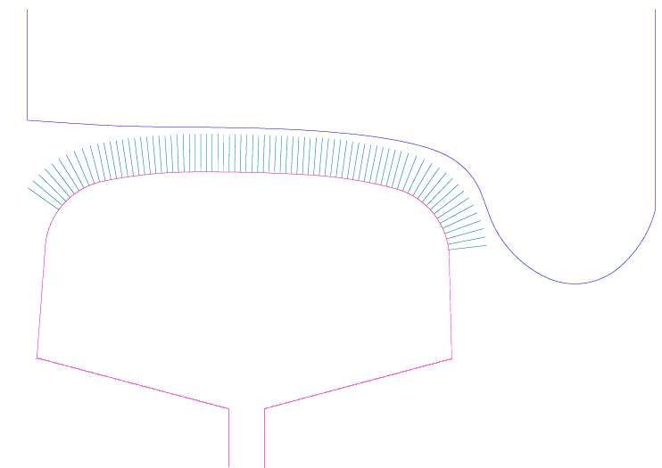
Before this coupling can be created the variables describing the track irregularities tral111r.y, tral111r.z, tral111r.vy and tral111r.vz must be defined. These variables can for example be created in function func tral_interp_spline.
 coupl creep_tanel_springs_1  c_name
              `body1' +-`a1 +-`b1 +-`h1
              `body2' +-`a2 +-`b2 +-`h2
               esys dire           # Euler system and direction of action
            +-`tral111r.y          # Lateral position track irregularity
            +-`tral111r.z          # Vertical position track irregularity
            +-`tral111r.vy         # Lateral velocity track irregularity
            +-`tral111r.vz         # Vertical velocity track irregularity
            +-`ro                  # Wheel rolling radius, will vary for OOR-wheels
               iorient             # Orientation of profiles +1=left, -1=right
            +-`mu                  # Friction coefficient in contact patch
            +-`mulfact_nux         # Longitudinal creep relaxation due to contaminated surfaces
            +-`mulfact_nuy         # Lateral      creep relaxation due to contaminated surfaces
            +-`mulfact_spin        # Spin         creep relaxation due to contaminated surfaces
            +-`kz_winkler          # Normal stiffness as in the Winkler bed
            +-`kz_tanel_1          # Vert. interconnection coupling in x- and y- direction
            +-`kx_fastsim          # Long. stiffn. equals parameter 1/L1 in Fastsim
            +-`kx_tanel_1          # Long. interconnection coupling in x-direction
            +-`kx_tanel_2          # Long. interconnection coupling in y-direction
            +-`ky_fastsim          # Lat. stiffn. equals parameter 1/L2 in Fastsim
            +-`ky_tanel_1          # Lat. interconnection coupling in y-direction
            +-`ky_tanel_2          # Lat. interconnection coupling in x-direction
            +-`cz_winkler          # Wheel/rail damping normal to the contact surface
               wheel_prof          # Wheel profile defined via a memory field, e.g. func intpl_r
               nl_brush            # Number of brushes in longitudinal direction on rail head
               xl_brush            # Distance between brushes in longitudinal direction
               rail_prof           # Rail profile defined via a memory field, e.g. func intpl_r
| c_name | = | Name of the coupling created. |
| body1 | = | Name of body no. 1, which the coupling is connected to. |
| a1,b1,h1 | = | The coupling's attachment coordinate in body 1, expressed in body 1's local coordinate system lsys. |
| body2 | = | Name of body no. 2 to which the coupling connects. |
| a2,b2,h2 | = | The coupling's attachment coordinate in body 2, expressed in body 2's local coordinate system lsys. |
| esys | = | The coordinate system in which the coupling force will be calculated. |
| dire | = | Working direction for the coupling end connected to body1. The only valid direction for coupling creep_tanel_springs_1 is 'm'. |
| tral111r.y | = | Lateral irregularity to be applied between body1 and body2 |
| tral111r.z | = | Vertical irregularity to be applied between body1 and body2 |
| tral111r.vy | = | Speed of the lateral irregularity between body1 and body2 |
| tral111r.vz | = | Speed of the vertical irregularity between body1 and body2 |
| ro | = | The longitudinal curve radius in the contact patch. |
| iorient | = | The orientation of the wheel and rail profile. Normally wheel- and rail- profiles are measured from track center line and out, which makes both profiles look as left handed profiles. The user can with this input data mirror the profiles on the right side of the track, without generate special right handed profiles. |
| mu | = | Friction coefficient in contact patch. |
| mulfact_nux | = | Creep reduction factor due to contamination and asperities in the contact surface. mulfact_nux only affects longitudinal creep. |
| mulfact_nuy | = | Creep reduction factor due to contamination and asperities in the contact surface. mulfact_nuy only affects lateral creep. |
| mulfact_spin | = | Creep reduction factor due to contamination and asperities in the contact surface. mulfact_spin only affects spin creep. |
| kz_winkler | = | The normal stiffness per brush. |
| kz_tanel_1 | = | Vert. interconnection coupling in x- and y- direction |
| kx_fastsim | = | Long. stiffn. equals parameter 1/L1 in Fastsim |
| kx_tanel_1 | = | Long. interconnection coupling in x-direction |
| kx_tanel_2 | = | Long. interconnection coupling in y-direction |
| ky_fastsim | = | Lat. stiffn. equals parameter 1/L2 in Fastsim |
| ky_tanel_1 | = | Lat. interconnection coupling in y-direction |
| ky_tanel_2 | = | Lat. interconnection coupling in x-direction |
| cz_winkler | = | Wheel/rail damping normal to the contact surface |
| wheel_prof | = | Wheel profile defined via a memory field, e.g. func intpl_r |
| nl_brush | = | Number of brushes in longitudinal direction on rail head |
| xl_brush | = | Distance between brushes in longitudinal direction |
| rail_prof | = | Rail profile defined via a memory field, e.g. func intpl_r |
Variables generated in the main memory:
Input variables:
| c_name.a1 | = | Attachment coordinate in x-direction on body 1. |
| c_name.b1 | = | Attachment coordinate in y-direction on body 1. |
| c_name.h1 | = | Attachment coordinate in z-direction on body 1. |
| c_name.a2 | = | Attachment coordinate in x-direction on body 2. |
| c_name.b2 | = | Attachment coordinate in y-direction on body 2. |
| c_name.h2 | = | Attachment coordinate in z-direction on body 2. |
| c_name.slip_area | = | Relative size of the slip zone in the contact patch. |
| c_name.Fnx | = | Longitudinal creep force, in plane with the contact surface. A positive value gives a positive force on body1. |
| c_name.Fny | = | Lateral creep force, in plane with the contact surface. A positive value gives a positive force on body1. |
Generated variables containing forces and moment, acting on body1 and body2:
| c_name.F1x | = | Longitudinal force acting on body1. |
| c_name.F1y | = | Lateral force acting on body1. |
| c_name.F1z | = | Vertical force acting on body1. |
| c_name.M1f | = | Roll moment acting on body1. |
| c_name.M1k | = | Pitch moment acting on body1. |
| c_name.M1p | = | Yaw moment acting on body1. |
| c_name.F2x | = | Longitudinal force acting on body2. |
| c_name.F2y | = | Lateral force acting on body2. |
| c_name.F2z | = | Vertical force acting on body2. |
| c_name.M2f | = | Roll moment acting on body2. |
| c_name.M2k | = | Pitch moment acting on body2. |
| c_name.M2p | = | Yaw moment acting on body2. |
c_type = `coupler_1`
Creates a coupling between two bodies. The force - displacement relationship is described with two non-linear curves, a loading curve and an unloading curve. The main usage for this coupling is to model coupler forces between car-bodies.
 coupl coupler_1  c_name
              `body1' +-`a1 +-`b1 +-`h1
              `body2' +-`a2 +-`b2 +-`h2
               esys dire
               speed_load       force_load
               speed_unload     force_unload
               Mech_Stop
| c_name | = | Name of the coupling created. |
| body1 | = | Name of body no. 1, which the coupling is connected to. |
| a1,b1,h1 | = | The coupling's attachment coordinate in body 1, expressed in body 1's local coordinate system lsys. |
| body2 | = | Name of body no. 2 to which the coupling connects. |
| a2,b2,h2 | = | The coupling's attachment coordinate in body 2, expressed in body 2's local coordinate system lsys. |
| esys | = | The coordinate system in which the coupling force will be calculated. |
| dire | = | Working direction for the coupling end connected to body1. The only valid direction for coupling c_magic_1 is 'm'. |
| speed_load | = | Speed over the buffer which defines that the buffer is subjected to loading. |
| force_load | = | Memory Field describing force-displacement under loading conditions. |
| speed_unload | = | Speed over the buffer which defines that the buffer is subjected to unloading. |
| force_unload | = | Memory Field describing force-displacement under unloading conditions. |
| Mech_Stop | = | Compression displacement when the longitudinal mechanical stop is getting engaged. |
When the speed over the coupling is less or equal to speed_unload, the force produced by "coupl coupler_1" follows the curve defined by force_unload. When the speed over the coupling is greater or equal to speed_load, the force produced by "coupl coupler_1" follows the curve defined by force_load. If the speed over the coupling is between speed_unload and speed_load, the force produced by "coupl coupler_1" is calculated according to:
forc= force_load* (-2*t3intp**3 + 3*t3intp**2) + force_unload*(2*t3intp**3 - 3*t3intp**2 + 1.d0)Where: t3intp= (c_name.v - speed_unload) / (speed_load - speed_unload)
The sign convention of the coupling deflection is defined as:
c_name.d= body_2.x - body_1.x
This means that if body_2 moves in positive direction more than body_1 does, the deformation is positive.
A positive deformation leads to a positive force, which is applied with a positive sign on body_1 and a negative sign on body_2.
For a buffer, positive deformation will stand for compression.
When the mechanical stop is engaged the force always follows force_load, regardless of the speed of the coupler.
When deflection exceeds Mech_Stop no extra spring force is added.
The property of the mechanical stop must be defined in memory field force_load.
Variables generated in the main memory:
Input variables:
| c_name.l | = | Length of the coupling. The length is calculated in the same direction as the coupling's direction of action. |
| c_name.m1 | = | Mass number of body 1. |
| c_name.a1 | = | Attachment coordinate in x-direction on body 1. |
| c_name.b1 | = | Attachment coordinate in y-direction on body 1. |
| c_name.h1 | = | Attachment coordinate in z-direction on body 1. |
| c_name.m2 | = | Mass number of body 2. |
| c_name.a2 | = | Attachment coordinate in x-direction on body 2. |
| c_name.b2 | = | Attachment coordinate in y-direction on body 2. |
| c_name.h2 | = | Attachment coordinate in z-direction on body 2. |
Output variables:
Deformation of the coupling:
| c_name.dx | = | In the x-direction of esys. |
| c_name.dy | = | In the y-direction of esys. |
| c_name.dz | = | In the z-direction of esys. |
| c_name.df | = | In the f-direction of esys. |
| c_name.dk | = | In the k-direction of esys. |
| c_name.dp | = | In the p-direction of esys. |
Force variables generated by the coupling:
| c_name.Fx | = | In the x-direction of esys. |
| c_name.Fy | = | In the y-direction of esys. |
| c_name.Fz | = | In the z-direction of esys. |
| c_name.Mf | = | In the f-direction of esys. |
| c_name.Mk | = | In the k-direction of esys. |
| c_name.Mp | = | In the p-direction of esys. |
If the working direction is c or cu, also the following variables are available:
| c_name.d | = | Deformation in the direction of the coupling. |
| c_name.v | = | Deformation speed over the coupling. |
| c_name.F | = | The generated force in the direction of the coupling. |
Generated force variables on connected bodies:
| c_name.F1x | = | Force acting on body #1 in the x-direction of body #1's lsys. |
| c_name.F1y | = | Force acting on body #1 in the y-direction of body #1's lsys. |
| c_name.F1z | = | Force acting on body #1 in the z-direction of body #1's lsys. |
| c_name.M1f | = | Moment acting on body #1 in the f-direction of body #1's lsys. |
| c_name.M1k | = | Moment acting on body #1 in the k-direction of body #1's lsys. |
| c_name.M1p | = | Moment acting on body #1 in the p-direction of body #1's lsys. |
| c_name.F2x | = | Force acting on body #2 in the x-direction of body #2's lsys. |
| c_name.F2y | = | Force acting on body #2 in the y-direction of body #2's lsys. |
| c_name.F2z | = | Force acting on body #2 in the z-direction of body #2's lsys. |
| c_name.M2f | = | Moment acting on body #2 in the f-direction of body #2's lsys. |
| c_name.M2k | = | Moment acting on body #2 in the k-direction of body #2's lsys. |
| c_name.M2p | = | Moment acting on body #2 in the p-direction of body #2's lsys. |
| – | Modeling coupler forces between car-bodies. |
c_type = `coupler_2`
Creates a coupling between two bodies. The force - displacement relationship is described with two non-linear curves, a loading curve and an unloading curve. A friction block with a series stiffness controls if the displacement - force relationship follows the loading or unloading curve. If the displacement The main usage for this coupling is to model coupler forces between car-bodies.
 coupl coupler_2  c_name
              `body1' +-`a1 +-`b1 +-`h1
              `body2' +-`a2 +-`b2 +-`h2
               esys dire
               series_stiffness
               force_load
               force_unload
               pdamp
| c_name | = | Name of the coupling created. |
| body1 | = | Name of body no. 1, which the coupling is connected to. |
| a1,b1,h1 | = | The coupling's attachment coordinate in body 1, expressed in body 1's local coordinate system lsys. |
| body2 | = | Name of body no. 2 to which the coupling connects. |
| a2,b2,h2 | = | The coupling's attachment coordinate in body 2, expressed in body 2's local coordinate system lsys. |
| esys | = | The coordinate system in which the coupling force will be calculated. |
| dire | = | Working direction for the coupling end connected to body1. The only valid direction for coupling c_magic_1 is 'm'. |
| series_stiffness | = | Elastic stiffness for small amplitudes. The coupler force is within force_unload and force_load. |
| force_load | = | Memory Field describing force-displacement under loading conditions. |
| force_unload | = | Memory Field describing force-displacement under unloading conditions. |
| pdamp | = | Parallel viscous damper. |
Force in series stiffness is calculated according to:
F_kf= series_stiffness*(c_name.d-pos_kf)
Where:
| c_name.d | = | Is the displacement over the coupling |
| pos_kf | = | Position of internal massless point |
| if (F_kf > force_load) | => | The internal massless point will move so the force c_name.F will be equal to force_load. |
| if (F_kf < force_unload) | => | The internal massless point will move so the force c_name.F will be equal to force_unload. |
| if (force_unload <= F_kf <= force_load) | => | Generated force c_name.F will be set equal to F_kf. |
Variables generated in the main memory:
Input variables:
| c_name.l | = | Length of the coupling. The length is calculated in the same direction as the coupling's direction of action. |
| c_name.m1 | = | Mass number of body 1. |
| c_name.a1 | = | Attachment coordinate in x-direction on body 1. |
| c_name.b1 | = | Attachment coordinate in y-direction on body 1. |
| c_name.h1 | = | Attachment coordinate in z-direction on body 1. |
| c_name.m2 | = | Mass number of body 2. |
| c_name.a2 | = | Attachment coordinate in x-direction on body 2. |
| c_name.b2 | = | Attachment coordinate in y-direction on body 2. |
| c_name.h2 | = | Attachment coordinate in z-direction on body 2. |
Output variables:
Deformation of the coupling:
| c_name.dx | = | In the x-direction of esys. |
| c_name.dy | = | In the y-direction of esys. |
| c_name.dz | = | In the z-direction of esys. |
| c_name.df | = | In the f-direction of esys. |
| c_name.dk | = | In the k-direction of esys. |
| c_name.dp | = | In the p-direction of esys. |
Force variables generated by the coupling:
| c_name.Fx | = | In the x-direction of esys. |
| c_name.Fy | = | In the y-direction of esys. |
| c_name.Fz | = | In the z-direction of esys. |
| c_name.Mf | = | In the f-direction of esys. |
| c_name.Mk | = | In the k-direction of esys. |
| c_name.Mp | = | In the p-direction of esys. |
If the working direction is c or cu, also the following variables are available:
| c_name.d | = | Deformation in the direction of the coupling. |
| c_name.v | = | Deformation speed over the coupling. |
| c_name.i | = | Position of internal massless point. |
| c_name.F | = | The generated force in the direction of the coupling. |
Generated force variables on connected bodies:
| c_name.F1x | = | Force acting on body #1 in the x-direction of body #1's lsys. |
| c_name.F1y | = | Force acting on body #1 in the y-direction of body #1's lsys. |
| c_name.F1z | = | Force acting on body #1 in the z-direction of body #1's lsys. |
| c_name.M1f | = | Moment acting on body #1 in the f-direction of body #1's lsys. |
| c_name.M1k | = | Moment acting on body #1 in the k-direction of body #1's lsys. |
| c_name.M1p | = | Moment acting on body #1 in the p-direction of body #1's lsys. |
| c_name.F2x | = | Force acting on body #2 in the x-direction of body #2's lsys. |
| c_name.F2y | = | Force acting on body #2 in the y-direction of body #2's lsys. |
| c_name.F2z | = | Force acting on body #2 in the z-direction of body #2's lsys. |
| c_name.M2f | = | Moment acting on body #2 in the f-direction of body #2's lsys. |
| c_name.M2k | = | Moment acting on body #2 in the k-direction of body #2's lsys. |
| c_name.M2p | = | Moment acting on body #2 in the p-direction of body #2's lsys. |
| – | Modeling coupler forces between car-bodies. |
c_type = `derailm_2`
Defines a contact element between two bodies.
The derailm_2-element can be used in simulations of derailment situations.
The following simple example shows a model of a disk brake and a track with sleepers and rails.
Number of nodes in the contact lines are undefined, the program reads coordinates until the command "End" is given. The two contact surfaces consists of vertical and horizontal lines only, sloping lines are not possible to define. Only one side of a contact line can produce contact force. In input data the user must define which side of the contact line that can produce the contact force, by giving a '+' or '-' sign before the next coordinate. Also in longitudinal direction a force will occur. The longitudinal force will be set equal to the contact force times the coefficient of friction mu_x. The longitudinal force acting on body1, will be in opposite direction relative to the longitudinal speed of body1.
 coupl derailm_2 `c_name'
                    `body1' +-`a1 +-`b1 +-`h1
                    `body2' +-`a2 +-`b2 +-`h2  esys
                  +-`stiffy  +-`stiffz
                  +-`dampny  +-`dampnz
                  +-`defmaxy +-`defmaxz
                  +-`mu_x
                    `Start_Dir_Surf1'   +-`c1,
                     (+|-),             +-`d1,
                     (+|-),             +-`c2,
                     (+|-),             +-`d3,
                     (+|-),             +-`c4,
                      , , , ,           , , , ,
                    `End1',             +-`cn
                    `Start_Dir_Surf2'   +-`C1,
                     (+|-),             +-`D1,
                     (+|-),             +-`C2,
                     (+|-),             +-`D3,
                     (+|-),             +-`C4,
                     , , , ,            , , , ,
                    `End2',             +-`Cn
| c_name | = | Name of the coupling created. |
| body1 | = | Name of body no. 1, which the coupling is connected to. |
| a1,b1,h1 | = | The coupling's attachment coordinate in body 1, expressed in body 1's local coordinate system lsys. |
| body2 | = | Name of body no. 2 to which the coupling connects. |
| a2,b2,h2 | = | The coupling's attachment coordinate in body 2, expressed in body 2's local coordinate system lsys. |
| esys | = | The coordinate system in which the coupling force will be calculated. |
| stiffy | = | Stiffness when two vertical contact lines meets. |
| stiffz | = | Stiffness when two horizontal contact lines meets. |
| dampny | = | Viscous damping when two vertical contact lines meets. Damping force is only calculated when the two surfaces are moving towards each other. Damping force are not calculated in tension. |
| dampnz | = | Damping when two horizontal contact lines meets. Damping force is only calculated when the two surfaces are moving towards each other. Damping force are not calculated in tension. |
| defmaxy | = | Max compression in lateral direction for the contact surfaces. If the compression is bigger than defmaxy, the surfaces are considered to be on the other side of each other. A warning message is printed on standard output if two surfaces are near to be pressed through each other. |
| defmaxz | = | Max compression in vertical direction, similar to defmaxy. |
| mu_x | = | Longitudinal coefficient of friction when two surfaces meets. |
| Start_Dir_Surf1, z0 | = | Defines the orientation of the first contact line on body1, and its start coordinate. Currently the only valid value is "Vertical". |
| (+|-), y1 | = | The sign "+" or "-" indicates on which side of the vertical contact line that gives a contact force. Coordinate "y1" gives the lateral position of the vertical contact line. |
| (+|-), z2 | = | At coordinate "z2", the contact line changes and becomes horizontal. The sign "+" or "-" indicates on which side of the horizontal line that gives contact force (N.B. positive Z-direction is downwards). Coordinate "z2" gives the hight of the horizontal contact line. |
| (+|-), y3 | = | At coordinate "y3", the contact line changes and becomes vertical again. The sign "+" or "-" indicates on which side of the vertical line that gives a contact force. Coordinate "y3" gives the lateral position of the vertical contact line. N.B. "y3" must be greater than "y1". |
| End1, z4 | = | The last coordinate is marked with the command "End1". The vertical contact line ends at coordinate "z4". The shape of the contact line on body1 must consist of exactly 5 coordinates. |
| Start_Dir_Surf2, Y0 | = | Defines the orientation of the first contact line on body2, and its start coordinate. Currently the only valid value is "Horizontal". |
| (+|-) Z# (+|-) Y# | = | The coordinates for contact line #2 are defined in the same way as for contact line #1. But for this line there are no limitation regarding number of coordinates. |
| (+|-) Z(n-1) | = | The second last coordinate for contact line #2. |
| End2, Yn | = | The last coordinate is marked with the command "End2". |
Variables generated in the main memory:
Input variables:
| c_name.m1 | = | Mass number of body 1. |
| c_name.a1 | = | Attachment coordinate in x-direction on body 1. |
| c_name.b1 | = | Attachment coordinate in y-direction on body 1. |
| c_name.h1 | = | Attachment coordinate in z-direction on body 1. |
| c_name.m2 | = | Mass number of body 2. |
| c_name.a2 | = | Attachment coordinate in x-direction on body 2. |
| c_name.b2 | = | Attachment coordinate in y-direction on body 2. |
| c_name.h2 | = | Attachment coordinate in z-direction on body 2. |
| c_name.ky | = | Lateral stiffness stiffy. |
| c_name.kz | = | Vertical stiffness stiffz. |
| c_name.cy | = | Lateral damping dampny. |
| c_name.cz | = | Vertical damping dampnz. |
| c_name.defmaxy | = | Max compression in lateral direction. |
| c_name.defmaxy | = | Max compression in vertical direction. |
| c_name.mux | = | Longitudinal friction. |
Output variables:
Deformation of the coupling:
| c_name.dx | = | In the x-direction of esys. |
| c_name.dy | = | In the y-direction of esys. |
| c_name.dz | = | In the z-direction of esys. |
| c_name.df | = | In the f-direction of esys. |
| c_name.dk | = | In the k-direction of esys. |
| c_name.dp | = | In the p-direction of esys. |
Force variables generated by the coupling:
| c_name.Fx | = | In the x-direction of esys. |
| c_name.Fy | = | In the y-direction of esys. |
| c_name.Fz | = | In the z-direction of esys. |
| c_name.Mf | = | In the f-direction of esys. |
| c_name.Mk | = | In the k-direction of esys. |
| c_name.Mp | = | In the p-direction of esys. |
Generated force variables on connected bodies:
| c_name.F1x | = | Force acting on body1 in the x-direction of body1's lsys. |
| c_name.F1y | = | Force acting on body1 in the y-direction of body1's lsys. |
| c_name.F1z | = | Force acting on body1 in the z-direction of body1's lsys. |
| c_name.M1f | = | Moment acting on body1 in the f-direction of body1's lsys. |
| c_name.M1k | = | Moment acting on body1 in the k-direction of body1's lsys. |
| c_name.M1p | = | Moment acting on body1 in the p-direction of body1's lsys. |
| c_name.F2x | = | Force acting on body2 in the x-direction of body2's lsys. |
| c_name.F2y | = | Force acting on body2 in the y-direction of body2's lsys. |
| c_name.F2z | = | Force acting on body2 in the z-direction of body2's lsys. |
| c_name.M2f | = | Moment acting on body2 in the f-direction of body2's lsys. |
| c_name.M2k | = | Moment acting on body2 in the k-direction of body2's lsys. |
| c_name.M2p | = | Moment acting on body2 in the p-direction of body2's lsys. |
Other variables generated by the coupling:
| c_name.Hsurf | = | Active surface horizontal force body1. |
| c_name.Vsurf | = | Active surface vertical force body2. |
| c_name.dmaxy | = | Deformation of the surface which gives the largest horizontal force. |
| c_name.dmaxz | = | Deformation of the surface which gives the largest vertical force. |
| – | Coupling derailm_2 has mainly been designed for simulations in a derailment situation. |
Defines a stiffness coupling between two masses.
The stiffness property is read from a pre-defined property.
A variant of coupl k is named coupl k_preZ.
In coupl k_preZ program CALC automatically calculates the
nominal vertical prestress force in the coupling,
in order to keep the connecting masses at zero vertical level.
Springs which are connected in direction `c` or `cu` may not have the length 0(zero), as the value zero does not have any direction.
 coupl k  `c_name' `body1' +-`a1 +-`b1 +-`h1
                   `body2' +-`a2 +-`b2 +-`h2
                    p_+-`property `esys' `dire`
| c_name | = | Name of the coupling created. |
| body1 | = | Name of body no. 1, which the coupling is connected to. |
| a1,b1,h1 | = | The coupling's attachment coordinate in body 1, expressed in body 1's local coordinate system lsys. |
| body2 | = | Name of body no. 2 to which the coupling connects. |
| a2,b2,h2 | = | The coupling's attachment coordinate in body 2, expressed in body 2's local coordinate system lsys. |
| property | = | Pre-defined coupling property. |
| esys | = | The coordinate system in which the coupling force will be calculated. |
| dire | = | `x`,`cx`, y`,`cy`,`z`,`cz`, `f`,`k`,`p`, `c`,`cu`, `m` The coupling's direction of action in esys. In addition to the Cartesian coordinates, are the directions `c`, `cu`, `cx`, `cz`, and `m`. Direction `c` refers to the direction specified by the coupling's attachment points, i.e the force runs in the direction of the element. The transformation matrix is calculated in the input reading phase of the program. The same transformation matrix is then used during the entire calculation. Direction `cu` has a similar function as `c`, the difference being that the transformation matrix is updated continuously as the bodies move. The directions of activity `cx`, `cy`, or `cz` refer to the same directions as `x`, `y`, or `z` but the coupling's nominal length is eliminated on calculation of the coupling's deformation and force. The direction `m` refers to the matrix direction, all 6 coordinate directions of the attachment points are calculated. Direction `m` requires p_lin36 or p_lin144 as coupling properties. |
Variables generated in the main memory:
Input variables:
| c_name.l | = | Length of the coupling. The length is calculated in the same direction as the coupling's direction of action. |
| c_name.m1 | = | Mass number of body 1. |
| c_name.a1 | = | Attachment coordinate in x-direction on body 1. |
| c_name.b1 | = | Attachment coordinate in y-direction on body 1. |
| c_name.h1 | = | Attachment coordinate in z-direction on body 1. |
| c_name.m2 | = | Mass number of body 2. |
| c_name.a2 | = | Attachment coordinate in x-direction on body 2. |
| c_name.b2 | = | Attachment coordinate in y-direction on body 2. |
| c_name.h2 | = | Attachment coordinate in z-direction on body 2. |
Output variables:
Deformation of the coupling:
| c_name.dx | = | In the x-direction of esys. |
| c_name.dy | = | In the y-direction of esys. |
| c_name.dz | = | In the z-direction of esys. |
| c_name.df | = | In the f-direction of esys. |
| c_name.dk | = | In the k-direction of esys. |
| c_name.dp | = | In the p-direction of esys. |
Force variables generated by the coupling:
| c_name.Fx | = | In the x-direction of esys. |
| c_name.Fy | = | In the y-direction of esys. |
| c_name.Fz | = | In the z-direction of esys. |
| c_name.Mf | = | In the f-direction of esys. |
| c_name.Mk | = | In the k-direction of esys. |
| c_name.Mp | = | In the p-direction of esys. |
If the working direction is c or cu, also the following variables are available:
| c_name.d | = | Deformation in the direction of the coupling. |
| c_name.F | = | The generated force in the direction of the coupling. |
Generated force variables on connected bodies:
| c_name.F1x | = | Force acting on body #1 in the x-direction of body #1's lsys. |
| c_name.F1y | = | Force acting on body #1 in the y-direction of body #1's lsys. |
| c_name.F1z | = | Force acting on body #1 in the z-direction of body #1's lsys. |
| c_name.M1f | = | Moment acting on body #1 in the f-direction of body #1's lsys. |
| c_name.M1k | = | Moment acting on body #1 in the k-direction of body #1's lsys. |
| c_name.M1p | = | Moment acting on body #1 in the p-direction of body #1's lsys. |
| c_name.F2x | = | Force acting on body #2 in the x-direction of body #2's lsys. |
| c_name.F2y | = | Force acting on body #2 in the y-direction of body #2's lsys. |
| c_name.F2z | = | Force acting on body #2 in the z-direction of body #2's lsys. |
| c_name.M2f | = | Moment acting on body #2 in the f-direction of body #2's lsys. |
| c_name.M2k | = | Moment acting on body #2 in the k-direction of body #2's lsys. |
| c_name.M2p | = | Moment acting on body #2 in the p-direction of body #2's lsys. |
| – |
Modeling a bushing. Define a coupling without length, i.e. give the same position for both ends of the coupling. Define the property via coupl p_lin36 or coupl p_lin144. Set the working direction of the coupling equal to m. |
| – |
Modeling of the stiffness in a traction rod. Define a coupling with length. Define a one-dimensional property with coupl p_lin, coupl p_nlin, coupl p_nlin_s, coupl p_nlin_t or coupl p_nlin_st. Set the working direction of the coupling equal to c or cu. |
| – |
Modeling of chevron elements. When measuring the stiffness of two chevron elements coupled in parallel, three effective stiffnesses kx, ky and kz can be measured. Enter the stiffnesses in a p_lin36 property. Set the working direction of the coupling equal to m. |
| – |
Modeling of stops. Define a coupling without length, i.e. give the same position for both ends of the coupling. Define a non-linear property with coupl p_nlin, coupl p_nlin_s, coupl p_nlin_t or coupl p_nlin_st. Set zero stiffness for zero deflection. Set the working direction of the coupling equal to x, y or z. |
| – |
Anti-roll bar. Define a coupling without length, i.e. give the same position for both ends of the coupling. Define a one-dimensional property with coupl p_lin, coupl p_nlin, coupl p_nlin_s, coupl p_nlin_t or coupl p_nlin_st. Set the working direction of the coupling equal to f. |
Defines a stiffness coupling between two masses.
The stiffness property is taken read a pre-defined property.
A variant of coupl k_l is named coupl k_l_preZ.
In coupl k_l_preZ program CALC automatically calculates the
nominal vertical prestress force in the coupling,
in order to keep the connecting masses at zero vertical level.
The stiffness can be given a small rotation angle relative, to the coordinate axis in esys. The rotation between esys and the coupling is linear (cos(fi)=1 and sin(fi)=fi).
 coupl k_l  `c_name' `body1' +-`a1 +-`b1 +-`h1
                     `body2' +-`a2 +-`b2 +-`h2
                      p_+-`property `esys' `dire`
                      +-`fi +-`chi +-`psi
| c_name | = | Name of the coupling created. |
| body1 | = | Name of body no. 1, which the coupling is connected to. |
| a1,b1,h1 | = | The coupling's attachment coordinate in body 1, expressed in body 1's local coordinate system lsys. |
| body2 | = | Name of body no. 2 to which the coupling connects. |
| a2,b2,h2 | = | The coupling's attachment coordinate in body 2, expressed in body 2's local coordinate system lsys. |
| property | = | Pre-defined coupling property. |
| esys | = | The coordinate system in which the coupling force will be calculated. |
| dire | = | `x`, `y`, `z`, `f`, `k`, `p`, `m`. Working direction for the damper in esys. In addition to the Cartesian coordinates, the user also can choose direction `m`. Direction `m` means matrix direction, displacements in all 6 coordinate directions in both attachment points are calculated. Direction `m` requires the coupling properties p_lin36 or p_lin144. |
| fi,chi,psi | = | The rotation angles from esys to the damper. The angle fi sets the rotation round the x-axis, angle chi sets the rotation round the y-axis and finally angle psi sets the rotation round the z-axis. |
Variables generated in the main memory:
Input variables:
| c_name.l | = | Length of the coupling. The length is calculated in the same direction as the coupling's direction of action. |
| c_name.m1 | = | Mass number of body 1. |
| c_name.a1 | = | Attachment coordinate in x-direction on body 1. |
| c_name.b1 | = | Attachment coordinate in y-direction on body 1. |
| c_name.h1 | = | Attachment coordinate in z-direction on body 1. |
| c_name.m2 | = | Mass number of body 2. |
| c_name.a2 | = | Attachment coordinate in x-direction on body 2. |
| c_name.b2 | = | Attachment coordinate in y-direction on body 2. |
| c_name.h2 | = | Attachment coordinate in z-direction on body 2. |
Output variables:
Deformation of the coupling:
| c_name.dx | = | In the rotated x-direction. |
| c_name.dy | = | In the rotated y-direction. |
| c_name.dz | = | In the rotated z-direction. |
| c_name.df | = | In the rotated f-direction. |
| c_name.dk | = | In the rotated k-direction. |
| c_name.dp | = | In the rotated p-direction. |
Force variables generated by the coupling:
| c_name.Fx | = | In the rotated x-direction. |
| c_name.Fy | = | In the rotated y-direction. |
| c_name.Fz | = | In the rotated z-direction. |
| c_name.Mf | = | In the rotated f-direction. |
| c_name.Mk | = | In the rotated k-direction. |
| c_name.Mp | = | In the rotated p-direction. |
Generated force variables on connected bodies:
| c_name.F1x | = | Force acting on body #1 in the x-direction of body #1's lsys. |
| c_name.F1y | = | Force acting on body #1 in the y-direction of body #1's lsys. |
| c_name.F1z | = | Force acting on body #1 in the z-direction of body #1's lsys. |
| c_name.M1f | = | Moment acting on body #1 in the f-direction of body #1's lsys. |
| c_name.M1k | = | Moment acting on body #1 in the k-direction of body #1's lsys. |
| c_name.M1p | = | Moment acting on body #1 in the p-direction of body #1's lsys. |
| c_name.F2x | = | Force acting on body #2 in the x-direction of body #2's lsys. |
| c_name.F2y | = | Force acting on body #2 in the y-direction of body #2's lsys. |
| c_name.F2z | = | Force acting on body #2 in the z-direction of body #2's lsys. |
| c_name.M2f | = | Moment acting on body #2 in the f-direction of body #2's lsys. |
| c_name.M2k | = | Moment acting on body #2 in the k-direction of body #2's lsys. |
| c_name.M2p | = | Moment acting on body #2 in the p-direction of body #2's lsys. |
| – | Coupling k_l can be used in the same way as coupling coupl k. In addition to coupling k this coupling can be oriented a small angle of rotation relative to the coordinate axles of esys. This extra rotation angle is only valid if the working direction of the coupling is x, y, z, f, k, p or m |
Defines a stiffness coupling between two masses.
The stiffness property is read from a pre-defined property.
A variant of coupl k_r is named coupl k_r_preZ.
In coupl k_r_preZ program CALC automatically calculates the
nominal vertical prestress force in the coupling,
in order to keep the connecting masses at zero vertical level.
The spring can be rotated in a large angle relative to the coordinate axis of esys. The rotation between esys and the coupling are non-linear, by using sinus and cosinus functions in the transformation matrix. The rotation angles must be given in the right order, because these rotations do not commute.
 coupl k_r  `c_name' `body1' +-`a1 +-`b1 +-`h1
                     `body2' +-`a2 +-`b2 +-`h2
                      p_+-`property `esys' `dire`
                      +-`fi +-`chi +-`psi
| c_name | = | Name of the coupling created. |
| body1 | = | Name of body no. 1, which the coupling is connected to. |
| a1,b1,h1 | = | The coupling's attachment coordinate in body 1, expressed in body 1's local coordinate system lsys. |
| body2 | = | Name of body no. 2 to which the coupling connects. |
| a2,b2,h2 | = | The coupling's attachment coordinate in body 2, expressed in body 2's local coordinate system lsys. |
| property | = | Pre-defined coupling property. |
| esys | = | The coordinate system in which the coupling force will be calculated. |
| dire | = | `x`, `y`, `z`, `f`, `k`, `p`, `m`. Working direction for the coupling in esys. In addition to the Cartesian coordinates, the user also can choose direction `m`. Direction `m` means matrix direction, displacements in all 6 coordinate directions in both attachment points are calculated. Direction `m` requires the coupling properties p_lin36 or p_lin144. |
| fi,chi,psi | = | The procedure for angle rotation esys to the coupling is as follows:
|
Variables generated in the main memory:
Input variables:
| c_name.l | = | Length of the coupling. The length is calculated in the same direction as the coupling's direction of action. |
| c_name.m1 | = | Mass number of body 1. |
| c_name.a1 | = | Attachment coordinate in x-direction on body 1. |
| c_name.b1 | = | Attachment coordinate in y-direction on body 1. |
| c_name.h1 | = | Attachment coordinate in z-direction on body 1. |
| c_name.m2 | = | Mass number of body 2. |
| c_name.a2 | = | Attachment coordinate in x-direction on body 2. |
| c_name.b2 | = | Attachment coordinate in y-direction on body 2. |
| c_name.h2 | = | Attachment coordinate in z-direction on body 2. |
Output variables:
Deformation of the coupling:
| c_name.dx | = | In the rotated x-direction. |
| c_name.dy | = | In the rotated y-direction. |
| c_name.dz | = | In the rotated z-direction. |
| c_name.df | = | In the rotated f-direction. |
| c_name.dk | = | In the rotated k-direction. |
| c_name.dp | = | In the rotated p-direction. |
Force variables generated by the coupling:
| c_name.Fx | = | In the rotated x-direction. |
| c_name.Fy | = | In the rotated y-direction. |
| c_name.Fz | = | In the rotated z-direction. |
| c_name.Mf | = | In the rotated f-direction. |
| c_name.Mk | = | In the rotated k-direction. |
| c_name.Mp | = | In the rotated p-direction. |
Generated force variables on connected bodies:
| c_name.F1x | = | Force acting on body #1 in the x-direction of body #1's lsys. |
| c_name.F1y | = | Force acting on body #1 in the y-direction of body #1's lsys. |
| c_name.F1z | = | Force acting on body #1 in the z-direction of body #1's lsys. |
| c_name.M1f | = | Moment acting on body #1 in the f-direction of body #1's lsys. |
| c_name.M1k | = | Moment acting on body #1 in the k-direction of body #1's lsys. |
| c_name.M1p | = | Moment acting on body #1 in the p-direction of body #1's lsys. |
| c_name.F2x | = | Force acting on body #2 in the x-direction of body #2's lsys. |
| c_name.F2y | = | Force acting on body #2 in the y-direction of body #2's lsys. |
| c_name.F2z | = | Force acting on body #2 in the z-direction of body #2's lsys. |
| c_name.M2f | = | Moment acting on body #2 in the f-direction of body #2's lsys. |
| c_name.M2k | = | Moment acting on body #2 in the k-direction of body #2's lsys. |
| c_name.M2p | = | Moment acting on body #2 in the p-direction of body #2's lsys. |
| – | Coupling k_r can be used in the same way as coupling coupl k. In addition to coupling k this coupling can be oriented a large angle of rotation relative to the coordinate axles of esys. This extra rotation angle is only valid if the working direction of the coupling is x, y, z, f, k, p or m |
c_type = `k12_b1`
Defines a stiffness coupling between two masses of type m_rigid_12.
The stiffness property is read from a pre-defined property.
The coupling is always oriented according to mass body1.
 coupl k12_b1  `c_name' `body1' +-`a1 +-`b1 +-`h1
                        `body2' +-`a2 +-`b2 +-`h2
                        `dire` `property'
| c_name | = | Name of the coupling created. |
| body1 | = | Name of body no. 1, which the coupling is connected to. |
| a1,b1,h1 | = | The coupling's attachment coordinate in body 1, expressed in body 1's local coordinate system lsys. |
| body2 | = | Name of body no. 2 to which the coupling connects. |
| a2,b2,h2 | = | The coupling's attachment coordinate in body 2, expressed in body 2's local coordinate system lsys. |
| dire | = | `x`,`y`,`z`,`f`,`k`,`p`, `m` The coupling's direction of action in esys. The direction `m` refers to the matrix direction, all 6 coordinate directions of the attachment points are calculated. Direction `m` requires p_lin36 or p_lin144 as coupling properties. |
| property | = | Pre-defined coupling property. |
Variables generated in the main memory:
Input variables:
| c_name.l | = | Length of the coupling. The length is calculated in the same direction as the coupling's direction of action. |
| c_name.m1 | = | Mass number of body 1. |
| c_name.a1 | = | Attachment coordinate in x-direction on body 1. |
| c_name.b1 | = | Attachment coordinate in y-direction on body 1. |
| c_name.h1 | = | Attachment coordinate in z-direction on body 1. |
| c_name.m2 | = | Mass number of body 2. |
| c_name.a2 | = | Attachment coordinate in x-direction on body 2. |
| c_name.b2 | = | Attachment coordinate in y-direction on body 2. |
| c_name.h2 | = | Attachment coordinate in z-direction on body 2. |
Output variables:
Generated force variables on connected bodies:
| c_name.F1x | = | Force acting on mass1 in direction x according to fsys |
| c_name.F1y | = | Force acting on mass1 in direction y according to fsys |
| c_name.F1z | = | Force acting on mass1 in direction z according to fsys |
| c_name.M1f | = | Torque acting on mass1 in direction f according to mass1 |
| c_name.M1k | = | Torque acting on mass1 in direction k according to mass1 |
| c_name.M1p | = | Torque acting on mass1 in direction p according to mass1 |
| c_name.F2x | = | Force acting on mass2 in direction x according to fsys |
| c_name.F2y | = | Force acting on mass2 in direction y according to fsys |
| c_name.F2z | = | Force acting on mass2 in direction z according to fsys |
| c_name.M2f | = | Torque acting on mass2 in direction f according to mass2 |
| c_name.M2k | = | Torque acting on mass2 in direction k according to mass2 |
| c_name.M2p | = | Torque acting on mass2 in direction p according to mass2 |
Deformation of the coupling:
| c_name.dx1 | = | Direction x according to mass1 |
| c_name.dy1 | = | Direction y according to mass1 |
| c_name.dz1 | = | Direction z according to mass1 |
| c_name.df1 | = | Direction f according to mass1 |
| c_name.dk1 | = | Direction k according to mass1 |
| c_name.dp1 | = | Direction p according to mass1 |
Speed over the coupling:
| c_name.vx1 | = | Direction x according to mass1 |
| c_name.vy1 | = | Direction y according to mass1 |
| c_name.vz1 | = | Direction z according to mass1 |
| c_name.vf1 | = | Direction f according to mass1 |
| c_name.vk1 | = | Direction k according to mass1 |
| c_name.vp1 | = | Direction p according to mass1 |
Forces and torques in the coupling:
| c_name.Fx1 | = | Direction x according to mass1 |
| c_name.Fy1 | = | Direction y according to mass1 |
| c_name.Fz1 | = | Direction z according to mass1 |
| c_name.Mf1 | = | Direction f according to mass1 |
| c_name.Mk1 | = | Direction k according to mass1 |
| c_name.Mp1 | = | Direction p according to mass1 |
Deformation of the coupling:
| c_name.dx2 | = | Direction x according to mass2 |
| c_name.dy2 | = | Direction y according to mass2 |
| c_name.dz2 | = | Direction z according to mass2 |
| c_name.df2 | = | Direction f according to mass2 |
| c_name.dk2 | = | Direction k according to mass2 |
| c_name.dp2 | = | Direction p according to mass2 |
Speed over the coupling:
| c_name.vx2 | = | Direction x according to mass2 |
| c_name.vy2 | = | Direction y according to mass2 |
| c_name.vz2 | = | Direction z according to mass2 |
| c_name.vf2 | = | Direction f according to mass2 |
| c_name.vk2 | = | Direction k according to mass2 |
| c_name.vp2 | = | Direction p according to mass2 |
Forces and torques in the coupling:
| c_name.Fx2 | = | Direction x according to mass2 |
| c_name.Fy2 | = | Direction y according to mass2 |
| c_name.Fz2 | = | Direction z according to mass2 |
| c_name.Mf2 | = | Direction f according to mass2 |
| c_name.Mk2 | = | Direction k according to mass2 |
| c_name.Mp2 | = | Direction p according to mass2 |
c_type = `k12_f`
Defines a stiffness coupling between two masses of type m_rigid_12.
The stiffness property is read from a pre-defined property.
The coupling is defined relative to the fixed coordinate system fsys.
 coupl k12_f  `c_name' `body1' +-`a1 +-`b1 +-`h1
                       `body2' +-`a2 +-`b2 +-`h2
                       `dire` `property'
| c_name | = | Name of the coupling created. |
| body1 | = | Name of body no. 1, which the coupling is connected to. |
| a1,b1,h1 | = | The coupling's attachment coordinate in body 1, expressed in body 1's local coordinate system lsys. |
| body2 | = | Name of body no. 2 to which the coupling connects. |
| a2,b2,h2 | = | The coupling's attachment coordinate in body 2, expressed in body 2's local coordinate system lsys. |
| dire | = | `x`,`y`,`z`,`f`,`k`,`p`, `m`, 'c', 'cu' The coupling's direction of action in fsys. Direction `c` means that the coupling is orientated according to its attachment points in the beginning of the simulation time= 0. Direction `cu` is the same as direction `c`, but its orientation is updated in every timestep. |
| property | = | Pre-defined coupling property. |
Variables generated in the main memory:
Input variables:
| c_name.l | = | Length of the coupling. The length is calculated in the same direction as the coupling's direction of action. |
| c_name.m1 | = | Mass number of body 1. |
| c_name.a1 | = | Attachment coordinate in x-direction on body 1. |
| c_name.b1 | = | Attachment coordinate in y-direction on body 1. |
| c_name.h1 | = | Attachment coordinate in z-direction on body 1. |
| c_name.m2 | = | Mass number of body 2. |
| c_name.a2 | = | Attachment coordinate in x-direction on body 2. |
| c_name.b2 | = | Attachment coordinate in y-direction on body 2. |
| c_name.h2 | = | Attachment coordinate in z-direction on body 2. |
Output variables:
Generated force variables on connected bodies:
| c_name.F1x | = | Force acting on mass1 in direction x according to fsys |
| c_name.F1y | = | Force acting on mass1 in direction y according to fsys |
| c_name.F1z | = | Force acting on mass1 in direction z according to fsys |
| c_name.M1f | = | Torque acting on mass1 in direction f according to mass1 |
| c_name.M1k | = | Torque acting on mass1 in direction k according to mass1 |
| c_name.M1p | = | Torque acting on mass1 in direction p according to mass1 |
| c_name.F2x | = | Force acting on mass2 in direction x according to fsys |
| c_name.F2y | = | Force acting on mass2 in direction y according to fsys |
| c_name.F2z | = | Force acting on mass2 in direction z according to fsys |
| c_name.M2f | = | Torque acting on mass2 in direction f according to mass2 |
| c_name.M2k | = | Torque acting on mass2 in direction k according to mass2 |
| c_name.M2p | = | Torque acting on mass2 in direction p according to mass2 |
Deformation of the coupling:
| c_name.dx | = | Direction x according to fsys |
| c_name.dy | = | Direction y according to fsys |
| c_name.dz | = | Direction z according to fsys |
| c_name.df | = | Direction f according to fsys |
| c_name.dk | = | Direction k according to fsys |
| c_name.dp | = | Direction p according to fsys |
| c_name.dx1 | = | Direction x according to mass1 |
| c_name.dy1 | = | Direction y according to mass1 |
| c_name.dz1 | = | Direction z according to mass1 |
| c_name.df1 | = | Direction f according to mass1 |
| c_name.dk1 | = | Direction k according to mass1 |
| c_name.dp1 | = | Direction p according to mass1 |
| c_name.dx2 | = | Direction x according to mass2 |
| c_name.dy2 | = | Direction y according to mass2 |
| c_name.dz2 | = | Direction z according to mass2 |
| c_name.df2 | = | Direction f according to mass2 |
| c_name.dk2 | = | Direction k according to mass2 |
| c_name.dp2 | = | Direction p according to mass2 |
Speed over the coupling:
| c_name.vx | = | Direction x according to fsys |
| c_name.vy | = | Direction y according to fsys |
| c_name.vz | = | Direction z according to fsys |
| c_name.vf | = | Direction f according to fsys |
| c_name.vk | = | Direction k according to fsys |
| c_name.vp | = | Direction p according to fsys |
| c_name.vx1 | = | Direction x according to mass1 |
| c_name.vy1 | = | Direction y according to mass1 |
| c_name.vz1 | = | Direction z according to mass1 |
| c_name.vf1 | = | Direction f according to mass1 |
| c_name.vk1 | = | Direction k according to mass1 |
| c_name.vp1 | = | Direction p according to mass1 |
| c_name.vx2 | = | Direction x according to mass2 |
| c_name.vy2 | = | Direction y according to mass2 |
| c_name.vz2 | = | Direction z according to mass2 |
| c_name.vf2 | = | Direction f according to mass2 |
| c_name.vk2 | = | Direction k according to mass2 |
| c_name.vp2 | = | Direction p according to mass2 |
Forces and moments in the coupling:
| c_name.Fx | = | Direction x according to fsys |
| c_name.Fy | = | Direction y according to fsys |
| c_name.Fz | = | Direction z according to fsys |
| c_name.Mf | = | Direction f according to fsys |
| c_name.Mk | = | Direction k according to fsys |
| c_name.Mp | = | Direction p according to fsys |
| c_name.Fx1 | = | Direction x according to mass1 |
| c_name.Fy1 | = | Direction y according to mass1 |
| c_name.Fz1 | = | Direction z according to mass1 |
| c_name.Mf1 | = | Direction f according to mass1 |
| c_name.Mk1 | = | Direction k according to mass1 |
| c_name.Mp1 | = | Direction p according to mass1 |
| c_name.Fx2 | = | Direction x according to mass2 |
| c_name.Fy2 | = | Direction y according to mass2 |
| c_name.Fz2 | = | Direction z according to mass2 |
| c_name.Mf2 | = | Direction f according to mass2 |
| c_name.Mk2 | = | Direction k according to mass2 |
| c_name.Mp2 | = | Direction p according to mass2 |
Orientation of the coupling:
| c_name.11 | = | Rotation matrix from the orientation of the coupling to fsys |
| c_name.21 | = | - " - |
| c_name.31 | = | - " - |
| c_name.12 | = | - " - |
| c_name.22 | = | - " - |
| c_name.32 | = | - " - |
| c_name.13 | = | - " - |
| c_name.23 | = | - " - |
| c_name.33 | = | - " - |
c_type = `k3`, `k3_preZ`
Defines a stiffness coupling between two masses, the stiffness properties is read from pre-defined properties. Coupling k3 is mainly developed for the modeling of standing vertically prestressed coil-springs. As input data the user only gives plain longitudinal, lateral and vertical stiffnesses. When measuring the longitudinal and lateral stiffnesses of the coil-spring it is important that the spring is subjected to a pure shear deformation. For a detailed description of the k3-coupling, please see the separate theory report "Calculation of coil springs, subjected to vertical load." in Swedish "Behandling av fjädrar vars infästningar ej är momentfria och som uppbär tyngd genom sig."
A variant of coupl k3 is named coupl k3_preZ.
In coupl k3_preZ program CALC automatically calculates the
nominal vertical prestress force in the coupling,
in order to keep the connecting masses at zero vertical level.
 coupl k3  `c_name' `body1' +-`a1 +-`b1 +-`h1
                    `body2' +-`a2 +-`b2 +-`h2
                     p_+-`property_x  p_+-`property_y  p_+-`property_z
                     +-`hstat +-`rf `esys' `dire`
| c_name | = | Name of the coupling created. |
| body1 | = | Name of body no. 1 to which the coupling connects. Body 1 is the body which is supported by the coupling. |
| a1,b1,h1 | = | The coordinate for the upper surface of the coupling, which is the surface which connects to body1. |
| body2 | = | Name of body no. 2 to which the coupling connects. Body 2 supports the coupling and also the weight of body1. |
| a2,b2,h2 | = | The coordinate for the upper surface of the coupling, i.e. the same as a1,b,h1. |
| property_x | = | Stiffness in the X-direction when the spring is subjected to only X-deformation. The upper and lower surfaces of the spring must both be kept horizontal. |
| property_y | = | Stiffness in the Y-direction when the spring is subjected to only Y-deformation. The upper and lower surfaces of the spring must both be kept horizontal. |
| property_z | = | Stiffness in the Z-direction when the spring is subjected to only Z-deformation. |
| hstat | = | Height of the spring when all masses are in their equilibrium state. |
| rf | = | Relative distance from the upper surface of the spring to the point of inflexion. The absolute distance is calculated as rf*hstat. |
| esys | = | The coordinate system in which the coupling force will be calculated. |
| dire | = | `m` is the only direction valid for this coupling. |
Variables generated in the main memory:
Input variables:
| c_name.m1 | = | Mass number of body 1. |
| c_name.a1 | = | Attachment coordinate in x-direction on body 1. |
| c_name.b1 | = | Attachment coordinate in y-direction on body 1. |
| c_name.h1 | = | Attachment coordinate in z-direction on body 1. |
| c_name.m2 | = | Mass number of body 2. |
| c_name.a2 | = | Attachment coordinate in x-direction on body 2. |
| c_name.b2 | = | Attachment coordinate in y-direction on body 2. |
| c_name.h2 | = | Attachment coordinate in z-direction on body 2. |
Output variables:
Deformation of the coupling:
| c_name.dx | = | In the x-direction of esys. |
| c_name.dy | = | In the y-direction of esys. |
| c_name.dz | = | In the z-direction of esys. |
| c_name.df | = | In the f-direction of esys. |
| c_name.dk | = | In the k-direction of esys. |
| c_name.dp | = | In the p-direction of esys. |
Force variables generated by the coupling:
| c_name.Fx | = | In the x-direction of esys. |
| c_name.Fy | = | In the y-direction of esys. |
| c_name.Fz | = | In the z-direction of esys. |
| c_name.Mf | = | In the f-direction of esys. |
| c_name.Mk | = | In the k-direction of esys. |
| c_name.Mp | = | In the p-direction of esys. |
Generated force variables on connected bodies:
| c_name.F1x | = | Force acting on body #1 in the x-direction of body #1's lsys. |
| c_name.F1y | = | Force acting on body #1 in the y-direction of body #1's lsys. |
| c_name.F1z | = | Force acting on body #1 in the z-direction of body #1's lsys. |
| c_name.M1f | = | Moment acting on body #1 in the f-direction of body #1's lsys. |
| c_name.M1k | = | Moment acting on body #1 in the k-direction of body #1's lsys. |
| c_name.M1p | = | Moment acting on body #1 in the p-direction of body #1's lsys. |
| c_name.F2x | = | Force acting on body #2 in the x-direction of body #2's lsys. |
| c_name.F2y | = | Force acting on body #2 in the y-direction of body #2's lsys. |
| c_name.F2z | = | Force acting on body #2 in the z-direction of body #2's lsys. |
| c_name.M2f | = | Moment acting on body #2 in the f-direction of body #2's lsys. |
| c_name.M2k | = | Moment acting on body #2 in the k-direction of body #2's lsys. |
| c_name.M2p | = | Moment acting on body #2 in the p-direction of body #2's lsys. |
| – | Coupling k3 is a convenient coupling element for modeling coil springs which is subjected to a vertical load. A coil spring has several off-diagonal stiffnesses connecting the lateral, longitudinal and bending behavior of the spring. The user can define a k-coupling with a p_lin144-property if the user has measured or by hand calculated all the off-diagonal components in the stiffness matrix. By using the k3-coupling the user only has to define three stiffnesses longitudinal shear stiffness, lateral shear stiffness and vertical compression. The k3-coupling will from these stiffnesses calculate all the off-diagonal components assuming that each section of the coil spring is perpendicular to the normal bending line of the spring. |
In the drawing the height of the coil-spring is
hstat
The free length of the spring is
hfree:
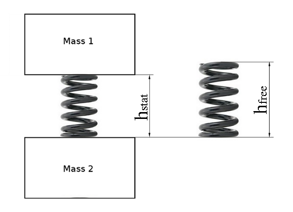
Give input data according to the following:
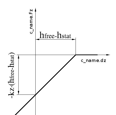
 coupl p_nlin  property_z      0.                   # Spring height according to drawing
               0.            `-kz*(hfree-hdraw)`    # gives a spring force of -kz*(hfree-hdraw)
              `hfree-hdraw`    0.                   # The coil-spring cannot take tension force
               1e3             0.
Reference Manuals
Calc menu
Input Data Menu
Coupl Menu
c_type = `k3_l`, `k3_l_preZ`
Defines a stiffness coupling between two masses similar to k3. In addition to k3, coupl k3_l can rotate relative esys. When the coupling rotates, its stiffness matrix and prestess force vector follows the rotation.
A variant of coupl k3_l is named coupl k3_l_preZ.
In coupl k3_l_preZ program CALC automatically calculates the
nominal vertical prestress force in the coupling,
in order to keep the connecting masses at zero vertical level.
 coupl k3_l  `c_name' `body1' +-`a1 +-`b1 +-`h1
                      `body2' +-`a2 +-`b2 +-`h2
                       p_+-`property_x  p_+-`property_y  p_+-`property_z
                       +-`h +-`rf `esys' `dire`
                       +-`fi +-`chi +-`psi
| c_name | = | Name of the coupling created. |
| body1 | = | Name of body no. 1 to which the coupling connects. Body 1 is the body which is supported by the coupling. |
| a1,b1,h1 | = | The coordinate for the upper surface of the coupling, which is the surface which connects to body1. |
| body2 | = | Name of body no. 2 to which the coupling connects. Body 2 supports the coupling and also the weight of body1. |
| a2,b2,h2 | = | The coordinate for the upper surface of the coupling, i.e. the same as a1,b,h1. |
| property_x | = | Stiffness in the X-direction when the spring is subjected to only X-deformation. The upper and lower surfaces of the spring must both be kept horizontal. |
| property_y | = | Stiffness in the Y-direction when the spring is subjected to only Y-deformation. The upper and lower surfaces of the spring must both be kept horizontal. |
| property_z | = | Stiffness in the Z-direction when the spring is subjected to only Z-deformation. |
| h | = | Height between the two connection surfaces of the spring. |
| rf | = | Relative distance from the upper surface of the spring to the point of inflexion. The absolute distance is calculated as rf*h. |
| esys | = | The coordinate system in which the coupling force shall be calculated. |
| dire | = | `m` is the only valid direction for this type of coupling. |
| fi,chi,psi | = | The rotation angles from the coordinate system esys to the rotated position of the k3_l-coupling. |
The output variables, which are generated in the output data field, have the same name as the variables generated by coupling k3. However the deformation of the coupling and the forces generated by the coupling are oriented in the direction of the spring.
| – | Coupling k3_l can be used in the same way as coupling coupl k3. In addition to coupling k3 this coupling can be oriented a small angle of rotation relative to the coordinate axles of esys. A secondary suspension consisting of coil springs standing on a bogie will tilt due to the motions of the bogie. In this case coupling k3_l is very useful, because it can be rotated a small angle relative to esys. The small rotation angles of the coil spring is equal to the rotation angles of the bogie. |
c_type = `k3_r`, `k3_r_preZ`
Defines a stiffness coupling between two masses similar to k3. In addition to k3, coupl k3_r can rotate large angles relative esys. When the coupling rotates, its stiffness matrix and prestess force vector follows the rotation.
A variant of coupl k3_r is named coupl k3_r_preZ.
In coupl k3_r_preZ program CALC automatically calculates the
nominal vertical prestress force in the coupling,
in order to keep the connecting masses at zero vertical level.
 coupl k3_r  `c_name' `body1' +-`a1 +-`b1 +-`h1
                      `body2' +-`a2 +-`b2 +-`h2
                       p_+-`property_x  p_+-`property_y  p_+-`property_z
                       +-`h +-`rf `esys' `dire`
                       +-`fi +-`chi +-`psi
| c_name | = | Name of the coupling created. |
| body1 | = | Name of body no. 1 to which the coupling connects. Body 1 is the body which is supported by the coupling. |
| a1,b1,h1 | = | The coordinate for the upper surface of the coupling, which is the surface which connects to body1. |
| body2 | = | Name of body no. 2 to which the coupling connects. Body 2 supports the coupling and also the weight of body1. |
| a2,b2,h2 | = | The coordinate for the upper surface of the coupling, i.e. the same as a1,b,h1. |
| property_x | = | Stiffness in the X-direction when the spring is subjected to only X-deformation. The upper and lower surfaces of the spring must both be kept horizontal. |
| property_y | = | Stiffness in the Y-direction when the spring is subjected to only Y-deformation. The upper and lower surfaces of the spring must both be kept horizontal. |
| property_z | = | Stiffness in the Z-direction when the spring is subjected to only Z-deformation. |
| h | = | Height between the two connection surfaces of the spring. |
| rf | = | Relative distance from the upper surface of the spring to the point of inflexion. The absolute distance is calculated as rf*h. |
| esys | = | The coordinate system in which the coupling force shall be calculated. |
| dire | = | `m` is the only valid direction for this type of coupling. |
| fi,chi,psi | = | The rotation angles from the coordinate system esys to the
rotated position of the k3_l-coupling. As large angles do not commute
the user must know how the rotation is made in the program.
The procedure for angle rotations is as follows:
|
The output variables, which are generated in the output data field, have the same name as the variables generated by coupling k3. However the deformation of the coupling and the forces generated by the coupling are oriented in the direction of the spring.
| – | Coupling k3_r can be used in the same way as coupling coupl k3. In addition to coupling k3 this coupling can be oriented a large angle of rotation relative to the coordinate axles of esys. The coupling is especially useful if the coil spring is measured in a vertical position, but mounted in the vehicle in a large angle relative to esys of the vehicle. By using the k3-coupling the user has the possibility to orient the coil spring in any direction he/she wants to. |
c_type = `km`, `km_preZ`
Defines a stiffness coupling between two masses.
Coupling `km` is similar to coupl 'k',
but the user can control if the coupling shall generate moments on attached masses or not
A variant of coupl km is named coupl km_preZ.
In coupl km_preZ program CALC automatically calculates the
nominal vertical prestress force in the coupling,
in order to keep the connecting masses at zero vertical level.
Springs which are connected in direction `c` or `cu` may not have the length 0(zero), as the value zero does not have any direction.
 coupl km `c_name' `body1' +-`a1 +-`b1 +-`h1
                   `body2' +-`a2 +-`b2 +-`h2
                   `property' `esys' `dire`  conn1  conn2
| c_name | = | Name of the coupling created. |
| body1 | = | Name of body no. 1, which the coupling is connected to. |
| a1,b1,h1 | = | The coupling's attachment coordinate in body 1, expressed in body 1's local coordinate system lsys. |
| body2 | = | Name of body no. 2 to which the coupling connects. |
| a2,b2,h2 | = | The coupling's attachment coordinate in body 2, expressed in body 2's local coordinate system lsys. |
| property | = | Pre-defined coupling property. |
| esys | = | The coordinate system in which the coupling force will be calculated. |
| dire | = |
`x`,`cx`, y`,`cy`,`z`,`cz`, `f`,`k`,`p`, `c`,`cu`, `m` The coupling's direction of action in esys. In addition to the Cartesian coordinates, are the directions `c`, `cu`, `cx`, `cz`, and `m`. Direction `c` refers to the direction specified by the coupling's attachment points, i.e the force runs in the direction of the element. The transformation matrix is calculated in the input reading phase of the program. The same transformation matrix is then used during the entire calculation. Direction `cu` has a similar function as `c`, the difference being that the transformation matrix is updated continuously as the bodies move. The directions of activity `cx`, `cy`, or `cz` refer to the same directions as `x`, `y`, or `z` but the coupling's nominal length is eliminated on calculation of the coupling's deformation and force. The direction `m` refers to the matrix direction, all 6 coordinate directions of the attachment points are calculated. Direction `m` requires p_lin36 or p_lin144 as coupling properties. |
| conn1 | = |
A three digit code for how moments from the coupling shall be transferred to mass #1.
The figure 0 in the three digit code, stands for zero moment in the attachment point.
The figure 1 in the three digit code, stands for full moment in the attachment point.
The first digit controls the moment in roll direction.
The Second digit controls the moment in pitch direction.
The third digit controls the moment in yaw direction. Example: The code '101' stands for moment in roll and yaw directions, but free in pitch. |
| conn2 | = | A three digit code for how moments from the coupling shall be transferred to mass #2. The conn2 code works in the same way as the conn1 code does. |
Variables generated in the main memory are the same as for coupl k.
| – | The km coupling can be used as coupl k. With the possibility to remove moments in attachment points, this coupling can be used for attaching springs directly to a wheelset without modeling an axle box as a separate mass. |
c_type = `km_l`
Defines a stiffness coupling between two masses. The coupling is very similar to the km coupling, but in the km_l coupling the user has the possibility to rotate the stiffness a small angle.
 coupl km_l  `c_name' `body1' +-`a1 +-`b1 +-`h1
                      `body2' +-`a2 +-`b2 +-`h2
                      `property' `esys' `dire`
                      `fi  `chi  `psi
                       conn1  conn2
| c_name | = | Name of the coupling created. |
| body1 | = | Name of body no. 1, which the coupling is connected to. |
| a1,b1,h1 | = | The coupling's attachment coordinate in body 1, expressed in body 1's local coordinate system lsys. |
| body2 | = | Name of body no. 2 to which the coupling connects. |
| a2,b2,h2 | = | The coupling's attachment coordinate in body 2, expressed in body 2's local coordinate system lsys. |
| property | = | Pre-defined stiffness property. |
| esys | = | The coordinate system in which the coupling force will be calculated. |
| dire | = |
`x`, `y`, `z`, `f`, `k`, `p`, `m` Direction in esys, which the coupling acts in. |
| fi,chi,psi | = | The rotation angles from the coordinate system esys to the rotated position of the km_l-coupling. |
| conn1 | = |
A three digit code for how moments from the coupling shall be transferred to mass #1.
The figure 0 in the three digit code, stands for zero moment in the attachment point.
The figure 1 in the three digit code, stands for full moment in the attachment point.
The first digit controls the moment in roll direction.
The Second digit controls the moment in pitch direction.
The third digit controls the moment in yaw direction. Example: The code '101' stands for moment in roll and yaw directions, but free in pitch. |
| conn2 | = | A three digit code for how moments from the coupling shall be transferred to mass #2. The conn2 code works in the same way as the conn1 code does. |
Variables generated in the main memory are the same as for coupling km.
| – | Coupling km_l can be used in the same way as coupl km. In addition to coupling km this coupling can be oriented a small angle of rotation relative to the coordinate axles of esys. |
c_type = `km_r`
Defines a stiffness coupling between two masses. The coupling is very similar to the km coupling, but in the km_r coupling the user has the possibility to rotate the stiffness a large angle.
 coupl km_r  `c_name' `body1' +-`a1 +-`b1 +-`h1
                      `body2' +-`a2 +-`b2 +-`h2
                      `property' `esys' `dire`
                      `fi  `chi  `psi
                       conn1  conn2
| c_name | = | Name of the coupling created. |
| body1 | = | Name of body no. 1, which the coupling is connected to. |
| a1,b1,h1 | = | The coupling's attachment coordinate in body 1, expressed in body 1's local coordinate system lsys. |
| body2 | = | Name of body no. 2 to which the coupling connects. |
| a2,b2,h2 | = | The coupling's attachment coordinate in body 2, expressed in body 2's local coordinate system lsys. |
| property | = | Pre-defined stiffness property. |
| esys | = | The coordinate system in which the coupling force will be calculated. |
| dire | = |
`x`, `y`, `z`, `f`, `k`, `p`, `m` Direction in esys, which the coupling acts in. |
| fi,chi,psi | = | The rotation angles from the coordinate system esys to the rotated position of the km_r-coupling. |
| conn1 | = |
A three digit code for how moments from the coupling shall be transferred to mass #1.
The figure 0 in the three digit code, stands for zero moment in the attachment point.
The figure 1 in the three digit code, stands for full moment in the attachment point.
The first digit controls the moment in roll direction.
The Second digit controls the moment in pitch direction.
The third digit controls the moment in yaw direction. Example: The code '101' stands for moment in roll and yaw directions, but free in pitch. |
| conn2 | = | A three digit code for how moments from the coupling shall be transferred to mass #2. The conn2 code works in the same way as the conn1 code does. |
Variables generated in the main memory are the same as for coupling km.
| – | Coupling km_r can be used in the same way as coupl km. In addition to coupling km this coupling can be oriented a large angle of rotation relative to the coordinate axles of esys. |
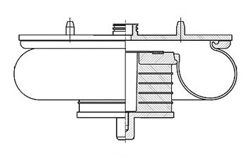
f_type = `k_air3_exp`
Defines a three-dimensional coupling between two masses. The coupling is especially designed for creating models of airbags in railway vehicles.
Horizontally the coupling comprises three parallel coupled parts:
| 1) | Elastic part: | Non-linear spring defined in the properties prop_kex and prop_key |
| 2) | Friction part: | Smooth Coulomb friction, parameters ffxmax and x2 |
| 3) | Viscous part: | Linear viscous damper cx, with series flexibility kvx |
Principal behavior of the airbag in horizontal direction:
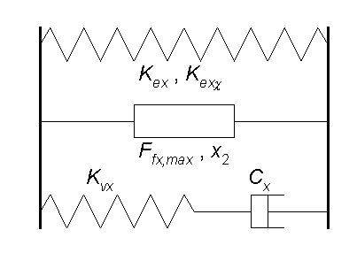
Vertically the coupling has similar properties,
but the viscous damper can be
modeled as a non-linear damper according to the following formula:
\( F= c_z \cdot sign( \dot z ) \cdot | \dot z | ^ \beta \)
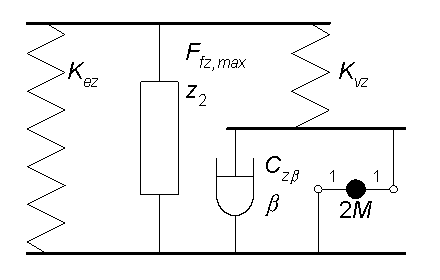
The theories of the k_air3_exp-coupling was developed by Mats Berg, Department of Vehicle Engineering, Royal Institute of Technology, Sweden. A detailed description of the coupling can be found in the report An airspring model for dynamic analysis of rail vehicles, TRITA-FKT Report 1999:32, ISSN 1103-470X, ISRN KTH/FKT/FR-99/32-SE. or A three-dimensional air-spring model with friction and orifice damping, Proc. 16th IAVSD Symposium on Dynamics of Vehicles on Road and Tracks, Vehicle System Dynamics, Vol. 33, pp. 528-539, ISSN 0042-3114, Swets & Zeitlinger 1999.
 coupl k_air3_exp `c_name' `mass_1' +-`a1 +-`b1 +-`h1
                           `mass_2' +-`a2 +-`b2 +-`h2
                           `esys' `dire`
                            prop_kex   +-`kexki_1
                            prop_key   +-`keyfi_1
                            prop_kez
                            +-`ffxmax  +-`x2    +-`ffzmax +-`z2
                            +-`kvx     +-`cx
                            +-`kvz     +-`czb   +-`beta   +-`m
| c_name | = | Name of the coupling created. |
| mass_1 | = | Name of mass no. 1, which the coupling is connected to. |
| a1,b1,h1 | = | The coupling's attachment coordinate in mass_1, expressed in mass_1's local coordinate system lsys. |
| mass_2 | = | Name of mass no. 2 to which the coupling connects. |
| a2,b2,h2 | = | The coupling's attachment coordinate in mass_2, expressed in mass_2's local coordinate system lsys. Apart from coupling k3 the coordinates a2,b2,h2 shall be the lower end of the airbag, and the distance between h1 and h2 is the height of the spring. |
| esys | = | The coordinate system in which the coupling displacements will be calculated. |
| dire | = | `m` is the only direction valid for this coupling. |
| prop_kex | = | Stiffness in the X-direction, when the airbag is subjected to only X-deformation. The upper and lower surfaces of the airbag must both be kept horizontal. |
| kexki_1 | = | Elastic stiffness which gives arise to a pitching moment of mass_1
due to a longitudinal displacement between mass_1 and mass_2.
The stiffness kexki_1 can be found by measuring the pitching moment between
mass_1 and airbag when the airbag is subjected to a pure longitudinal deformation. If no measurements are available, the value of kexki_1 can be calculated according to the following formula: kexki_1= (-c_name.F1z + prop_kex*(h2-h1))*rf Where "rf" tells how large portion of the moment that will be applied on mass_1. I.e. the remaining part of the moment will go to mass_2: kexki_2= (-c_name.F1z + prop_kex*(h2-h1))*(1-rf) The value of "rf" must be in the range [0-1]. Since positive z-axis is pointing downwards (in the same direction as the gravity), means that the sign of c_name.F1z in normally negative. |
| prop_key | = | Stiffness in the Y-direction when the spring is subjected to only Y-deformation. The upper and lower surfaces of the airbag must both be kept horizontal. |
| keyfi_1 | = | Elastic stiffness which gives arise to a rolling moment on mass_1
due to a lateral displacement between mass_1 and mass_2.
The stiffness keyfi can be found by measuring the rolling moment between
mass_1 and airbag when the airbag is subjected to a pure lateral deformation. If no measurements are available, the value of keyfi_1 can be calculated according to the following formula: keyfi_1= (c_name.F1z - prop_key*(h2-h1))*rf Where "rf" tells how large portion of the moment that will be applied on mass_1. I.e. the remaining part of the moment will go to mass_2: keyfi_2= (c_name.F1z - prop_key*(h2-h1))*(1-rf) The value of "rf" must be in the range [0-1]. Since positive z-axis is pointing downwards (in the same direction as the gravity), means that the value of c_name.F1z in normally negative. |
| prop_kez | = | Stiffness in the Z-direction when the spring is subjected to only Z-deformation. In property prop_kez the nominal vertical force is defined as a pre-stress force. |
| ffxmax | = | Maximum friction force in the horizontal plane. The friction force is smooth and ffxmax is the asymptotic friction force when the horizontal displacement is large. |
| x2 | = | The horizontal displacement defining where the friction force ffxmax/2. is obtained. |
| ffzmax | = | Maximum friction force in the vertical plane. The friction force is smooth and ffzmax is the asymptotic friction force when the vertical displacement is large. |
| z2 | = | The vertical displacement defining where the friction force ffzmax/2. is obtained. |
| kvx | = | Series flexibility in the longitudinal and lateral viscous dampers. |
| cx | = | Damping coefficient for the viscous dampers coupled between mass_1 and mass_2 in longitudinal and lateral direction |
| kvz | = | Series flexibility in the vertical viscous damper. |
| czb | = | Damping coefficient for the viscous damper coupled between mass_1 and mass_2 in vertical direction |
| beta | = | Exponent to the non-linear viscous damping in vertical direction, see formula above. |
| m | = | Effective mass coupled in parallel with the vertical viscous damper |
Variables generated in the main memory:
Input variables:
| c_name.l | = | Length of the coupling. The length is calculated in the same direction as the coupling's direction of action. |
| c_name.m1 | = | Number of mass_1. |
| c_name.a1 | = | Attachment coordinate in x-direction on mass_1. |
| c_name.b1 | = | Attachment coordinate in y-direction on mass_1. |
| c_name.h1 | = | Attachment coordinate in z-direction on mass_1. |
| c_name.m2 | = | Number of mass_2. |
| c_name.a2 | = | Attachment coordinate in x-direction on mass_2. |
| c_name.b2 | = | Attachment coordinate in y-direction on mass_2. |
| c_name.h2 | = | Attachment coordinate in z-direction on mass_2. |
Output variables:
Deformation of the coupling:
| c_name.dx | = | In the x-direction of esys. |
| c_name.dy | = | In the y-direction of esys. |
| c_name.dz | = | In the z-direction of esys. |
| c_name.df | = | In the f-direction of esys. |
| c_name.dk | = | In the k-direction of esys. |
| c_name.dp | = | In the p-direction of esys. |
Force variables generated by the coupling:
| c_name.Fx | = | In the x-direction of esys. |
| c_name.Fy | = | In the y-direction of esys. |
| c_name.Fz | = | In the z-direction of esys. |
| c_name.Mf | = | In the f-direction of esys. |
| c_name.Mk | = | In the k-direction of esys. |
| c_name.Mp | = | In the p-direction of esys. |
Generated force variables on connected bodies:
| c_name.F1x | = | Force acting on mass_1 in the x-direction of mass_1's lsys. |
| c_name.F1y | = | Force acting on mass_1 in the y-direction of mass_1's lsys. |
| c_name.F1z | = | Force acting on mass_1 in the z-direction of mass_1's lsys. |
| c_name.M1f | = | Moment acting on mass_1 in the f-direction of mass_1's lsys. |
| c_name.M1k | = | Moment acting on mass_1 in the k-direction of mass_1's lsys. |
| c_name.M1p | = | Moment acting on mass_1 in the p-direction of mass_1's lsys. |
| c_name.F2x | = | Force acting on mass_2 in the x-direction of mass_2's lsys. |
| c_name.F2y | = | Force acting on mass_2 in the y-direction of mass_2's lsys. |
| c_name.F2z | = | Force acting on mass_2 in the z-direction of mass_2's lsys. |
| c_name.M2f | = | Moment acting on mass_2 in the f-direction of mass_2's lsys. |
| c_name.M2k | = | Moment acting on mass_2 in the k-direction of mass_2's lsys. |
| c_name.M2p | = | Moment acting on mass_2 in the p-direction of mass_2's lsys. |
| – | Generation of a detailed model of an airspring element. |
f_type = `k_air3_mawa`
A coupling for modeling airbags in railway vehicles,
using equations for viscous flow in pipes.
The coupling is especially designed for creating models of airbags,
equipped with a pipe to an auxiliary air reservoir.
This airbag only considers the vertical stiffness of the airbag.
In order to take horizontal stiffness into effect,
please couple this coupling in parallel with coupl k_air3_exp.
In coupling coupl k_air3_exp, please set prop_kez, ffzmax and kvz all equal to 0 (zero).
The theories of the k_air3_mawa-coupling has been developed by Mattias Wallin.
The model consists of three major parts: the airbag, the auxiliary volume
and the pipe connecting the airbag to the auxiliary volume.
The mass of the air in the pipe is modeled with a second order differential equation.
Ref.: "s. E. Haaland, "Simple and Explicit Formulas for the
Friction Factor in Turbulent Pipe Flow" Fluids Eng.., March 1983, pp. 89-90.
| p_atm | = | 101300 | [Pa] | Atmospheric air pressure |
| mu273 | = | 1.71e-5 | [Ns/m2] | Absolute viscosity for air at 273 [K] |
| m_corr | = | 1.058 | [1] | Kinematic mass correction factor,due to the velocity variation from the mean velocity over the cross section for turbulent flow. |
The vertical force in k_air3_mawa is calculated by multiplying the current air pressure with the effective area of the airbag. Minus the force generated by the rubber bellow itself, which is in parallel with the air..
In series with the airbag an emergency spring is attached. The two springs are connected to each other via a massless node in the connection point.
 coupl k_air3_mawa `c_name' `c_name.m1' +-`c_name.a1 +-`c_name.b1 +-`c_name.h1
                            `c_name.m2' +-`c_name.a2 +-`c_name.b2 +-`c_name.h2
                            `esys' `dire`
                            +-`c_name.Stiffb   +-`c_name.F0
                            +-`c_name.Adia
                            +-`c_name.T0       +-`c_name.R
                            +-`c_name.A1       +-`c_name.V01
                            +-`c_name.Vres
                            +-`c_name.Lpipe    +-`c_name.dpipe   +-`c_name.epsp
                            +-`c_name.d_orif   +-`c_name.Kfacts
                            +-`c_name.kemer    +-`c_name.cemer
| c_name | = | Name of the coupling created. |
| c_name.m1 | = | Name of the first body that connects to the coupling. |
| c_name.a1 c_name.b1 c_name.h1 | = | The coupling's attachment coordinate in body 1, expressed in body 1's local coordinate system lsys. In longitudinal, lateral and vertical direction. |
| c_name.m2 | = | Name of the second body that connects to the coupling. |
| c_name.a2 c_name.b2 c_name.h2 | = | The coupling's attachment coordinate in body 2, expressed in body 2's local coordinate system lsys. Apart from coupling k3 the coordinates a2,b2,h2 shall be the lower end of the airbag, and the distance between h1 and h2 is the height of the spring. |
| esys | = | The coordinate system in which the coupling displacements will be calculated. |
| dire | = | `z` is the only direction valid for this coupling. |
| c_name.Stiffb | = | Vertical stiffness of the bellow membrane. The stiffness acts in parallel with the compressed air. |
| c_name.F0 | = | Nominal vertical force on the airbag [N]. In the simple case it is equal to the weight of the car-body times earth gravity divided by four. |
| c_name.Adia | = | Adiabatic index. If the process is considered to be isothermal, c_name.Adia shall be set equal to= 1. If the process is considered to be fully adiabatic, c_name.Adia shall be set equal to= 1.4. |
| c_name.T0 | = | Current working temperature of the airbag. The temperature has a great influence on the density of the air, which affects the total mass of the air. The temperature shall be given in the SI-unit [K]. |
| c_name.R | = | Specific gas constant for dry air= 287.058 [ J/kg/K ] |
| c_name.A1 | = | Airbag effective area [m2] |
| c_name.V01 | = | Volume of airbag at nominal vertical load c_name.F0. |
| c_name.Vres | = | Volume of auxiliary air reservoir [m3] |
| c_name.Lpipe | = | Length of air pipe [m] |
| c_name.dpipe | = | Diameter of air pipe [m] |
| c_name.epsp | = | Surface roughness inside of the air pipe [m]. (For steel tubes the recommended value is 46e-6) |
| c_name.d_orif | = | Diameter of orifice [m]. If no orifice is used set c_name.d_orif equal to c_name.dpipe. |
| c_name.Kfacts | = | Sum of losses from inlet, outlet, elbows. See information below, how to calculate c_name.Kfacts. |
| c_name.kemer | = | The vertical stiffness in the emergency spring in series with the airbag |
| c_name.cemer | = | Viscous damping in the emergency spring |
| Kloss | = | The same as c_name.Kfacts |
| Kin | = | 0.5 = Inlet loss for sharp-edged inlet |
| Kout | = | 1.0 = Outlet loss for sharp-edged outlet |
| Kelbow | = | Loss from all elbows according to table below |
Where each 90-degree elbow contributes to the sum according to:
| rpipe/dpipe | Kelbow |
|---|---|
| 1 | 0.38 |
| 2 | 0.24 |
| 3 | 0.20 |
| 4 | 0.18 |
| 5 | 0.16 |
| 6 | 0.14 |
| 7 | 0.13 |
| 8 | 0.13 |
| 10 | 0.15 |
| rpipe | = | The radius of the elbow |
| dpipe | = | The diameter of the pipe |
Variables generated in the main memory:
Input variables:
| c_name.m1 | = | Mass number of body 1. |
| c_name.a1 | = | Attachment coordinate in x-direction on body 1. |
| c_name.b1 | = | Attachment coordinate in y-direction on body 1. |
| c_name.h1 | = | Attachment coordinate in z-direction on body 1. |
| c_name.m2 | = | Mass number of body 2. |
| c_name.a2 | = | Attachment coordinate in x-direction on body 2. |
| c_name.b2 | = | Attachment coordinate in y-direction on body 2. |
| c_name.h2 | = | Attachment coordinate in z-direction on body 2. |
Output variables:
| c_name.l | = | Undeformed length of the coupling. |
| c_name.p0 | = | – c_name.F0 / c_name.A1 + 101300 [N/m2] Air pressure at nominal vertical load c_name.F0. (101300= "The Standard Atmosphere" 1[atm]) |
| c_name.ro0 | = | c_name.p0 / c_name.R / c_name.T0 Density of the air at temperature c_name.T0 and pressure c_name.p0. |
| c_name.rop | = | Instantaneous air density. |
| c_name.mu0 | = | 1.71d-5 * (c_name.T0/273.15)**0.7 Absolute viskosity of air at temperature c_name.T0. |
| c_name.nu0 | = | c_name.mu0 / c_name.ro0 Kinematic viskosity of air at temperature c_name.T0. |
| c_name.p | = | Instantaneous air pressure in bellow. |
| c_name.x1 | = | Deformation in bellow only. |
| c_name.xp | = | Position of the air in the pipe. |
| c_name.xpp | = | Speed of the air in the pipe. |
| c_name.xppp | = | Acceleration of the air in the pipe. |
| c_name.Reyn | = | Reynolds number which depends on the speed of the air flow in the pipe. |
| c_name.zemer | = | Deformation in emergency spring only. |
| c_name.vzemer | = | Speed in emergency spring only. |
| c_name.p_res | = | Air pressure in auxiliary air reservoir. |
Total deformations in the coupling, over both bellow and emergency spring:
| c_name.dx | = | In the x-direction of esys. |
| c_name.dy | = | In the y-direction of esys. |
| c_name.dz | = | In the z-direction of esys. |
| c_name.df | = | In the f-direction of esys. |
| c_name.dk | = | In the k-direction of esys. |
| c_name.dp | = | In the p-direction of esys. |
Force variables generated by the coupling:
| c_name.Fx | = | In the x-direction of esys. |
| c_name.Fy | = | In the y-direction of esys. |
| c_name.Fz | = | In the z-direction of esys. |
| c_name.Mf | = | In the f-direction of esys. |
| c_name.Mk | = | In the k-direction of esys. |
| c_name.Mp | = | In the p-direction of esys. |
Generated force variables on connected bodies:
| c_name.F1x | = | Force acting on body #1 in the x-direction of body #1's lsys. |
| c_name.F1y | = | Force acting on body #1 in the y-direction of body #1's lsys. |
| c_name.F1z | = | Force acting on body #1 in the z-direction of body #1's lsys. |
| c_name.M1f | = | Moment acting on body #1 in the f-direction of body #1's lsys. |
| c_name.M1k | = | Moment acting on body #1 in the k-direction of body #1's lsys. |
| c_name.M1p | = | Moment acting on body #1 in the p-direction of body #1's lsys. |
| c_name.F2x | = | Force acting on body #2 in the x-direction of body #2's lsys. |
| c_name.F2y | = | Force acting on body #2 in the y-direction of body #2's lsys. |
| c_name.F2z | = | Force acting on body #2 in the z-direction of body #2's lsys. |
| c_name.M2f | = | Moment acting on body #2 in the f-direction of body #2's lsys. |
| c_name.M2k | = | Moment acting on body #2 in the k-direction of body #2's lsys. |
| c_name.M2p | = | Moment acting on body #2 in the p-direction of body #2's lsys. |
| – | Generation of a detailed model of an airspring element with an auxiliary volume. |
| – | The model is especially useful in the design-stage where no measurements on the airbag are available. After measurements on the airbag has been done, the user can use the k_air3_exp-coupling. |
f_type = `k_air3_mawa2`
A coupling for modeling airbags in railway vehicles, using equations for viscous flow in pipes. The coupling is very similar to coupl k_air3_mawa but it has two auxiliary air reservoirs.
 coupl k_air3_mawa2 `c_name' `body1' +-`a1 +-`b1 +-`h1
                             `body2' +-`a2 +-`b2 +-`h2
                             `esys' `dire`
                             +-`c_name.Stiffb   +-`c_name.F0
                             +-`c_name.Adia
                             +-`c_name.T0       +-`c_name.R

                             +-`c_name.A1       +-`c_name.V01

                             +-`c_name.Vres1
                             +-`c_name.Lpipe1    +-`c_name.dpipe1  +-`c_name.epsp1
                             +-`c_name.d_orif1   +-`c_name.Kfacts1

                             +-`c_name.Vres2
                             +-`c_name.Lpipe2    +-`c_name.dpipe2  +-`c_name.epsp2
                             +-`c_name.d_orif2   +-`c_name.Kfacts2

                             +-`c_name.kemer     +-`c_name.cemer
| c_name | = | Name of the coupling created. |
| body1 | = | Name of body no. 1, which the coupling is connected to. |
| a1,b1,h1 | = | The coupling's attachment coordinate in body 1, expressed in body 1's local coordinate system lsys. |
| body2 | = | Name of body no. 2 to which the coupling connects. |
| a2,b2,h2 | = | The coupling's attachment coordinate in body 2, expressed in body 2's local coordinate system lsys. Apart from coupling k3 the coordinates a2,b2,h2 shall be the lower end of the airbag, and the distance between h1 and h2 is the height of the spring. |
| esys | = | The coordinate system in which the coupling displacements will be calculated. |
| dire | = | `z` is the only direction valid for this coupling. |
| c_name.Stiffb | = | The vertical stiffness of the bellow in parallel with the compressed air |
| c_name.F0 | = | Nominal vertical force on the airbag [N]. In the simple case it is equal to the weight of the car-body times earth gravity divided by four. |
| c_name.Adia | = | If the process is considered to be isothermal, c_name.Adia shall be set equal to= 1. If the process is considered to be fully adiabatic, c_name.Adia shall be set equal to= 1.4. |
| c_name.T0 | = | Current working temperature of the airbag. The temperature has a great influence on the density of the air, which affects the total mass of the air. The temperature shall be given in the SI-unit [K]. |
| c_name.R | = | Specific gas constant for dry air= 287 [ J/kg/K ] |
| c_name.A1 | = | Airbag effective area [m2]. |
| c_name.V01 | = | Volume of airbag [m3] |
| c_name.Vres1 | = | Volume of auxiliary air reservoir #1 [m3] |
| c_name.Lpipe1 | = | Length of air pipe #1 [m] |
| c_name.dpipe1 | = | diameter of air pipe #1 [m] |
| c_name.epsp1 | = | Surface roughness inside of the air pipe #1 [m]. (For steel tubes the recommended value is 46e-6) |
| c_name.d_orif1 | = | Diameter of orifice #1 [m]. If no orifice is used, set c_name.d_orif1 equal to c_name.dpipe1. |
| c_name.Kfacts1 | = | Sum of losses from inlet, outlet, elbows, etc in air pipe #1. How to calculate c_name.Kfacts1, see documenation under coupl k_air3_mawa |
| c_name.Vres2 | = | Volume of auxiliary air reservoir #2 [m3] |
| c_name.Lpipe2 | = | Length of air pipe #2 [m] |
| c_name.dpipe2 | = | diameter of air pipe #2 [m] |
| c_name.epsp2 | = | Surface roughness inside of the air pipe #2 [m]. (For steel tubes the recommended value is 46e-6) |
| c_name.d_orif2 | = | Diameter of orifice #2 [m]. If no orifice is used set c_name.d_orif2 equal to c_name.dpipe2. |
| c_name.Kfacts2 | = | Sum of losses from inlet, outlet, elbows, etc in air pipe #2. How to calculate c_name.Kfacts2, see documenation under coupl k_air3_mawa |
| c_name.kemer | = | The vertical stiffness in the emergency spring in series with the airbag |
| c_name.cemer | = | Viscous damping in the emergency spring |

f_type = `k_air4`
Defines a three-dimensional coupling between two masses.
The coupling comprises stiffness in all three directions x, y & z. In longitudinal and lateral direction the stiffnesses are linear. In vertical direction the coupling looks as follows:
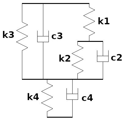
 coupl k_air4 `c_name'  `body1' +-`a1 +-`b1 +-`h1
                        `body2' +-`a2 +-`b2 +-`h2
                        `esys'
                         +-`Fx0  +-`Fy0  +-`Fz0
                         +-`kx   +-`cx
                         +-`ky   +-`cy
                         +-`k1   +-`k2   +-`c2
                         +-`k3   +-`c3   +-`k4   +-`c4
| c_name | = | Name of the coupling created. |
| body1 | = | Name of body no. 1, which the coupling is connected to. |
| a1,b1,h1 | = | The coupling's attachment coordinate in body 1, expressed in body 1's local coordinate system lsys. |
| body2 | = | Name of body no. 2 to which the coupling connects. |
| a2,b2,h2 | = | The coupling's attachment coordinate in body 2, expressed in body 2's local coordinate system lsys. Apart from coupling k3 the coordinates a2,b2,h2 shall be the lower end of the airbag, and the distance between h1 and h2 is the height of the spring. |
| esys | = | The coordinate system in which the coupling displacements will be calculated. |
| Fx0 | = | Prestress force in longitudinal direction, acting on body1 with positive sign and on body2 with negative sign. |
| Fy0 | = | Prestress force in lateral direction, acting on body1 with positive sign and on body2 with negative sign. |
| Fz0 | = | Prestress force in vertical direction, acting on body1 with positive sign and on body2 with negative sign. |
| kh | = | Linear stiffness in horizontal direction. |
| ch | = | Linear damping in horizontal direction. In parallel with stiffness kh. |
| k1 | = | Linear stiffness in vertical direction, see figure above. |
| k2 | = | Linear stiffness in vertical direction, see figure above. |
| c2 | = | Linear damping in vertical direction, see figure above. |
| k3 | = | Linear stiffness in vertical direction, see figure above. |
| c3 | = | Linear damping in vertical direction, see figure above. |
| k4 | = | Linear stiffness in vertical direction, see figure above. |
| c4 | = | Linear damping in vertical direction, see figure above. |
Variables generated in the main memory:
Input variables:
| c_name.l | = | Length of the coupling. The length is calculated in the same direction as the coupling's direction of action. |
| c_name.m1 | = | Mass number of body 1. |
| c_name.a1 | = | Attachment coordinate in x-direction on body 1. |
| c_name.b1 | = | Attachment coordinate in y-direction on body 1. |
| c_name.h1 | = | Attachment coordinate in z-direction on body 1. |
| c_name.m2 | = | Mass number of body 2. |
| c_name.a2 | = | Attachment coordinate in x-direction on body 2. |
| c_name.b2 | = | Attachment coordinate in y-direction on body 2. |
| c_name.h2 | = | Attachment coordinate in z-direction on body 2. |
Output variables:
Deformation of the coupling:
| c_name.dx | = | In the x-direction of esys. |
| c_name.dy | = | In the y-direction of esys. |
| c_name.dz | = | In the z-direction of esys. |
| c_name.df | = | In the f-direction of esys. |
| c_name.dk | = | In the k-direction of esys. |
| c_name.dp | = | In the p-direction of esys. |
Deformation velocities over the coupling:
| c_name.vx | = | In the x-direction of esys. |
| c_name.vy | = | In the y-direction of esys. |
| c_name.vz | = | In the z-direction of esys. |
| c_name.vf | = | In the f-direction of esys. |
| c_name.vk | = | In the k-direction of esys. |
| c_name.vp | = | In the p-direction of esys. |
Forces generated by the coupling:
| c_name.Fx | = | In the x-direction of esys. |
| c_name.Fy | = | In the y-direction of esys. |
| c_name.Fz | = | In the z-direction of esys. |
| c_name.Mf | = | In the f-direction of esys. |
| c_name.Mk | = | In the k-direction of esys. |
| c_name.Mp | = | In the p-direction of esys. |
Generated force variables on connected bodies:
| c_name.F1x | = | Force acting on body #1 in the x-direction of body #1's lsys. |
| c_name.F1y | = | Force acting on body #1 in the y-direction of body #1's lsys. |
| c_name.F1z | = | Force acting on body #1 in the z-direction of body #1's lsys. |
| c_name.M1f | = | Moment acting on body #1 in the f-direction of body #1's lsys. |
| c_name.M1k | = | Moment acting on body #1 in the k-direction of body #1's lsys. |
| c_name.M1p | = | Moment acting on body #1 in the p-direction of body #1's lsys. |
| c_name.F2x | = | Force acting on body #2 in the x-direction of body #2's lsys. |
| c_name.F2y | = | Force acting on body #2 in the y-direction of body #2's lsys. |
| c_name.F2z | = | Force acting on body #2 in the z-direction of body #2's lsys. |
| c_name.M2f | = | Moment acting on body #2 in the f-direction of body #2's lsys. |
| c_name.M2k | = | Moment acting on body #2 in the k-direction of body #2's lsys. |
| c_name.M2p | = | Moment acting on body #2 in the p-direction of body #2's lsys. |
| – | Modelling of airbags. |
c_type = `k_coil3`
Modeling of a vertically standing coil springs. The spring creates all off-diagonal elements in the stiffness matrix by itself. The user only defines stiffnesses in pure shear, pure compression, pure bending and pure yaw rotation.
| Vertical compression | Horizontal shearing | |
|---|---|---|
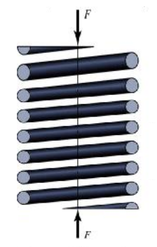 |
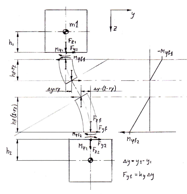 |
The spring is modeled as a 6x6 stiffness matrix with many off-diagonal elements ≠ 0. In addition, the stiffness values in the 6x6 matrix are not constant, they depend on the vertical and horizontal deformation of the spring.
 coupl k_coil3  `c_name' `body1' +-`a1 +-`b1 +-`h1
                         `body2' +-`a2 +-`b2 +-`h2
                          p_+-`property_x  p_+-`property_y  p_+-`property_z
                          p_+-`property_f  p_+-`property_k  p_+-`property_p
                          +-`hfree +-`hcomp +-`rf `esys' `dire`
| c_name | = | Name of the coupling created. |
| body1 | = | Upper body to which the coupling connects. |
| a1,b1,h1 | = | The coordinate for the upper surface of the coupling, which is the surface which connects to body1. |
| body2 | = | Lower body to which the coupling connects. |
| a2,b2,h2 | = | The coordinate for the lower surface of the coupling. |
| property_x | = | Stiffness under pure shearing in longitudinal direction. |
| property_y | = | Stiffness under pure shearing in lateral direction. |
| property_z | = | Stiffness under pure compression. |
| property_f | = | Stiffness under pure bending in rot-X direction. |
| property_k | = | Stiffness under pure bending in rot-Y direction. |
| property_p | = | Stiffness in pure rot-Z direction. |
| hfree | = | Free length of the spring (the spring cannot create tension forces). |
| hcomp | = | Compressed length of the spring (mechanic stop). |
| rf | = | Relative distance from the upper surface of the spring to the point of inflexion. The absolute distance is obtained by multiplying rf with the height of the spring. |
| esys | = | The coordinate system in which the coupling force will be calculated. |
| dire | = | `m` is the only direction valid for this coupling. |
Variables generated in the main memory:
Input variables:
| c_name.m1 | = | Mass number of body 1. |
| c_name.a1 | = | Attachment coordinate in x-direction on body 1. . |
| c_name.b1 | = | Attachment coordinate in y-direction on body 1. |
| c_name.h1 | = | Attachment coordinate in z-direction on body 1. |
| c_name.m2 | = | Mass number of body 2. |
| c_name.a2 | = | Attachment coordinate in x-direction on body 2. |
| c_name.b2 | = | Attachment coordinate in y-direction on body 2. |
| c_name.h2 | = | Attachment coordinate in z-direction on body 2. |
The attachment coordinates are expressed in the coordinate systems to where body 1 resp. body 2 belongs.
Output variables:
Deformation of the coupling:
| c_name.dx | = | In x-direction. |
| c_name.dy | = | In y-direction. |
| c_name.dz | = | In z-direction. |
| c_name.df | = | In f-direction. |
| c_name.dk | = | In k-direction. |
| c_name.dp | = | In p-direction. |
The deformations are expressed relative to the orientation of the spring. The matrix that rotates from esys to the orientation of the spring, is as follows:
         / 1 + ψ - χ \
  Res = | -ψ + 1 + φ  |
         \ χ - φ + 1 /
Where the angles has been calculated according to:
 φ= φ(body1)*rf + φ(body2)*(1-rf)
 χ= χ(body1)*rf + χ(body2)*(1-rf)
 ψ= ψ(body1)*rf + ψ(body2)*(1-rf)
Where:
φ(body1), χ(body1), ψ(body1)= Orientation of body #1
φ(body2), χ(body2), ψ(body2)= Orientation of body #2
rf = Relative distance to inflexion point. See input data arguments above.
Forces generated by the coupling:
| c_name.Fx | = | In x-direction. |
| c_name.Fy | = | In y-direction. |
| c_name.Fz | = | In z-direction. |
| c_name.Mf | = | In f-direction. |
| c_name.Mk | = | In k-direction. |
| c_name.Mp | = | In p-direction. |
The forces are also expressed relative to the orientation of the spring. Please see under deformations above.
Generated force variables on connected bodies:
| c_name.F1x | = | Force acting on body #1 in the x-direction of body #1's lsys. |
| c_name.F1y | = | Force acting on body #1 in the y-direction of body #1's lsys. |
| c_name.F1z | = | Force acting on body #1 in the z-direction of body #1's lsys. |
| c_name.M1f | = | Moment acting on body #1 in the f-direction of body #1's lsys. |
| c_name.M1k | = | Moment acting on body #1 in the k-direction of body #1's lsys. |
| c_name.M1p | = | Moment acting on body #1 in the p-direction of body #1's lsys. |
| c_name.F2x | = | Force acting on body #2 in the x-direction of body #2's lsys. |
| c_name.F2y | = | Force acting on body #2 in the y-direction of body #2's lsys. |
| c_name.F2z | = | Force acting on body #2 in the z-direction of body #2's lsys. |
| c_name.M2f | = | Moment acting on body #2 in the f-direction of body #2's lsys. |
| c_name.M2k | = | Moment acting on body #2 in the k-direction of body #2's lsys. |
| c_name.M2p | = | Moment acting on body #2 in the p-direction of body #2's lsys. |
| – | Coupling k_coil3 is a convenient coupling element for modeling coil springs which is subjected to a vertical load. A coil spring has several off-diagonal stiffnesses connecting the lateral, longitudinal and bending behavior of the spring. The user can define a k-coupling with a p_lin144-property if the user has measured or by hand calculated all the off-diagonal components in the stiffness matrix. By using the k_coil3-coupling the user only has to define six stiffnesses, see input data list above. The k_coil3-coupling will from six stiffnesses calculate all the off-diagonal components assuming that each section of the coil spring is perpendicular to the normal bending line of the spring. |
c_type = `kc`
Defines a coupling between two masses, the coupling comprises a damper with series flexibility. The components in the coupling are connected to each other according to the following figure:
The properties of the spring and damper are read from pre-defined properties. Couplings acting in direction `c` or `cu` may not have the length 0(zero), because the value zero does not have any direction.
 coupl kc  `c_name' `mass1' +-`a1 +-`b1 +-`h1
                    `mass2' +-`a2 +-`b2 +-`h2
                     p_+-`prop_k  p_+-`prop_c  `esys' `dire`
| c_name | = | Name of the coupling created. |
| mass1 | = | Name of mass no. 1, which the coupling is connected to. |
| a1,b1,h1 | = | The coupling's attachment coordinate in mass 1, expressed in mass 1's local coordinate system lsys. |
| mass2 | = | Name of mass no. 2 to which the coupling connects. |
| a2,b2,h2 | = | The coupling's attachment coordinate in mass 2, expressed in mass 2's local coordinate system lsys. |
| prop_k | = | Pre-defined stiffness property. |
| prop_c | = | Pre-defined damping property. N.B. prop_c must be of type p_lin, p_nlin or p_nlin_s, otherwise an error will occur and the program stops. |
| esys | = | The coordinate system in which the coupling force will be calculated. |
| dire | = | `x`, `y`, `z`, `f`, `k`, `p`, `c`, `cu` Direction in esys, which the coupling acts in. In addition to the Cartesian coordinates, there are the directions `c` and `cu`. Direction `c` refers to the direction specified by the coupling's attachment points, i.e the force runs in the direction of the element. The transformation matrix is calculated when the coupling is read in the input reading phase of the program. The same transformation matrix is then used during the entire calculation. Direction `cu` has a similar function as `c`, the difference being that the transformation matrix is updated continuously as the bodies move. |
Variables generated in the main memory:
Input variables:
| c_name.l | = | Length of the coupling. The length is calculated in the same direction as the coupling's direction of action. |
| c_name.m1 | = | Number of mass #1. |
| c_name.a1 | = | Attachment coordinate in x-direction on mass #1. |
| c_name.b1 | = | Attachment coordinate in y-direction on mass #1. |
| c_name.h1 | = | Attachment coordinate in z-direction on mass #1. |
| c_name.m2 | = | Number of mass 2. |
| c_name.a2 | = | Attachment coordinate in x-direction on mass #2. |
| c_name.b2 | = | Attachment coordinate in y-direction on mass #2. |
| c_name.h2 | = | Attachment coordinate in z-direction on mass #2. |
Output variables:
| c_name.i | = | The position of the internal degree of freedom in the coupling. |
| c_name.vi | = | The speed of the internal degree of freedom in the coupling. |
| c_name.d | = | Total deformation in spring + damper, in the direction of the coupling. |
| c_name.F | = | The generated force in the coupling. |
| c_name.dx | = | Velocity over the coupling in the x-direction. |
| c_name.dy | = | Velocity over the coupling in the y-direction. |
| c_name.dz | = | Velocity over the coupling in the z-direction. |
| c_name.df | = | Velocity over the coupling in the f-direction. |
| c_name.dk | = | Velocity over the coupling in the k-direction. |
| c_name.dp | = | Velocity over the coupling in the p-direction. |
Force variables generated by the coupling:
| c_name.Fx | = | Force in the x-direction. |
| c_name.Fy | = | Force in the y-direction. |
| c_name.Fz | = | Force in the z-direction. |
| c_name.Mf | = | Force in the f-direction. |
| c_name.Mk | = | Force in the k-direction. |
| c_name.Mp | = | Force in the p-direction. |
Generated force variables on connected bodies:
| c_name.F1x | = | Force acting on mass #1 in the x-direction of mass #1's lsys. |
| c_name.F1y | = | Force acting on mass #1 in the y-direction of mass #1's lsys. |
| c_name.F1z | = | Force acting on mass #1 in the z-direction of mass #1's lsys. |
| c_name.M1f | = | Moment acting on mass #1 in the f-direction of mass #1's lsys. |
| c_name.M1k | = | Moment acting on mass #1 in the k-direction of mass #1's lsys. |
| c_name.M1p | = | Moment acting on mass #1 in the p-direction of mass #1's lsys. |
| c_name.F2x | = | Force acting on mass #2 in the x-direction of mass #2's lsys. |
| c_name.F2y | = | Force acting on mass #2 in the y-direction of mass #2's lsys. |
| c_name.F2z | = | Force acting on mass #2 in the z-direction of mass #2's lsys. |
| c_name.M2f | = | Moment acting on mass #2 in the f-direction of mass #2's lsys. |
| c_name.M2k | = | Moment acting on mass #2 in the k-direction of mass #2's lsys. |
| c_name.M2p | = | Moment acting on mass #2 in the p-direction of mass #2's lsys. |
| – | Hydraulic dampers where the series flexibility of the damper must be considered. This is especially important when modeling yaw-dampers in railway vehicles. |
| – | Generation of simple rubber models where the kc-coupling is coupled in parallel with a k-coupling. These two couplings together will create a coupling with different static and dynamic stiffness, for more information please look in the documentation of program kc_prop. |
The transfer function for the kc-coupling can be written as:

| F= | The force produced by the kc-coupling. |
| c= | The damping coefficient of the damper. |
| k= | The stiffness in the series spring. |
| ω= | Excitation frequency in [rad/s]. |
| x= | The deformation of the kc-coupling. |
In the equation above it can be seen that for low frequencies the kc-coupling is acting as a damper, but for higher frequencies the kc-coupling is acting as a spring. The cut-off angular frequency for the kc-coupling is defined as:

c_type = `kce`
Defines a coupling between two masses, the coupling comprises a damper with series flexibility. Where the damper has an exponent factor \( F_c= prop\_c \cdot sign(\dot x) \cdot | \dot x| ^{\beta} \). The components in the coupling are connected to each other according to the following figure:
The properties of the spring and damper are read from pre-defined properties. Couplings acting in direction `c` or `cu` may not have the length 0(zero), because the value zero does not have any direction.
 coupl kc  `c_name' `mass1' +-`a1 +-`b1 +-`h1
                    `mass2' +-`a2 +-`b2 +-`h2
                     p_+-`prop_k  p_+-`prop_c  +-`beta  `esys' `dire`
| c_name | = | Name of the coupling created. |
| mass1 | = | Name of mass no. 1, which the coupling is connected to. |
| a1,b1,h1 | = | The coupling's attachment coordinate in mass 1, expressed in mass 1's local coordinate system lsys. |
| mass2 | = | Name of mass no. 2 to which the coupling connects. |
| a2,b2,h2 | = | The coupling's attachment coordinate in mass 2, expressed in mass 2's local coordinate system lsys. |
| prop_k | = | Pre-defined stiffness property. |
| prop_c | = | Pre-defined damping property. N.B. p_lin is the only valid property. |
| beta | = | Exponent factor. |
| esys | = | The coordinate system in which the coupling force will be calculated. |
| dire | = | `x`, `y`, `z`, `f`, `k`, `p`, `c`, `cu` Direction in esys, which the coupling acts in. In addition to the Cartesian coordinates, there are the directions `c` and `cu`. Direction `c` refers to the direction specified by the coupling's attachment points, i.e the force runs in the direction of the element. The transformation matrix is calculated when the coupling is read in the input reading phase of the program. The same transformation matrix is then used during the entire calculation. Direction `cu` has a similar function as `c`, the difference being that the transformation matrix is updated continuously as the bodies move. |
Variables generated in the main memory:
Input variables:
| c_name.l | = | Length of the coupling. The length is calculated in the same direction as the coupling's direction of action. |
| c_name.m1 | = | Number of mass #1. |
| c_name.a1 | = | Attachment coordinate in x-direction on mass #1. |
| c_name.b1 | = | Attachment coordinate in y-direction on mass #1. |
| c_name.h1 | = | Attachment coordinate in z-direction on mass #1. |
| c_name.m2 | = | Number of mass 2. |
| c_name.a2 | = | Attachment coordinate in x-direction on mass #2. |
| c_name.b2 | = | Attachment coordinate in y-direction on mass #2. |
| c_name.h2 | = | Attachment coordinate in z-direction on mass #2. |
Output variables:
| c_name.i | = | The position of the internal degree of freedom in the coupling. |
| c_name.vi | = | The speed of the internal degree of freedom in the coupling. |
| c_name.d | = | Total deformation in spring + damper, in the direction of the coupling. |
| c_name.F | = | The generated force in the coupling. |
| c_name.dx | = | Velocity over the coupling in the x-direction. |
| c_name.dy | = | Velocity over the coupling in the y-direction. |
| c_name.dz | = | Velocity over the coupling in the z-direction. |
| c_name.df | = | Velocity over the coupling in the f-direction. |
| c_name.dk | = | Velocity over the coupling in the k-direction. |
| c_name.dp | = | Velocity over the coupling in the p-direction. |
Force variables generated by the coupling:
| c_name.Fx | = | Force in the x-direction. |
| c_name.Fy | = | Force in the y-direction. |
| c_name.Fz | = | Force in the z-direction. |
| c_name.Mf | = | Force in the f-direction. |
| c_name.Mk | = | Force in the k-direction. |
| c_name.Mp | = | Force in the p-direction. |
Generated force variables on connected bodies:
| c_name.F1x | = | Force acting on mass #1 in the x-direction of mass #1's lsys. |
| c_name.F1y | = | Force acting on mass #1 in the y-direction of mass #1's lsys. |
| c_name.F1z | = | Force acting on mass #1 in the z-direction of mass #1's lsys. |
| c_name.M1f | = | Moment acting on mass #1 in the f-direction of mass #1's lsys. |
| c_name.M1k | = | Moment acting on mass #1 in the k-direction of mass #1's lsys. |
| c_name.M1p | = | Moment acting on mass #1 in the p-direction of mass #1's lsys. |
| c_name.F2x | = | Force acting on mass #2 in the x-direction of mass #2's lsys. |
| c_name.F2y | = | Force acting on mass #2 in the y-direction of mass #2's lsys. |
| c_name.F2z | = | Force acting on mass #2 in the z-direction of mass #2's lsys. |
| c_name.M2f | = | Moment acting on mass #2 in the f-direction of mass #2's lsys. |
| c_name.M2k | = | Moment acting on mass #2 in the k-direction of mass #2's lsys. |
| c_name.M2p | = | Moment acting on mass #2 in the p-direction of mass #2's lsys. |
| – | Modeling of dampers where the cut-off frequency don't agree with \( \omega_0= k/c \). |
| – | Hydraulic damped primary bush (HALL bush) |
f_type = `kckc`
Defines a coupling between two masses, the coupling comprises two dampers and two springs. The components in the coupling are connected to each other according to the following figure:

The properties of the springs and dampers are read from pre-defined properties. Couplings acting in direction `c` or `cu` may not have the length 0(zero), because the value zero does not have any direction.
 coupl kckc  `c_name' `body1' +-`a1 +-`b1 +-`h1
                      `body2' +-`a2 +-`b2 +-`h2
                      `prop_k1' `prop_c1' `prop_k2' `prop_c2'
                      `esys' `dire`
| c_name | = | Name of the coupling created. |
| body1 | = | Name of body no. 1, which the coupling is connected to. |
| a1,b1,h1 | = | The coupling's attachment coordinate in body 1, expressed in body 1's local coordinate system lsys. |
| body2 | = | Name of body no. 2 to which the coupling connects. |
| a2,b2,h2 | = | The coupling's attachment coordinate in body 2, expressed in body 2's local coordinate system lsys. |
| prop_k1 | = | Pre-defined stiffness property for stiffness number 1. |
| prop_c1 | = | Pre-defined damping property for damper number 1. NB! prop_c1 must be of type p_lin, otherwise an error will occur and the program stops. |
| prop_k2 | = | Pre-defined stiffness property for stiffness number 2. |
| prop_c2 | = | Pre-defined damping property for damper number 2. NB! prop_c2 must be of type p_lin, otherwise an error will occur and the program stops. |
| esys | = | The coordinate system in which the coupling force will be calculated. |
| dire | = | `x`, `y`, `z`, `f`, `k`, `p`, `c`, `cu` Direction in esys, which the coupling acts in. In addition to the Cartesian coordinates, there are the directions `c` and `cu`. Direction `c` refers to the direction specified by the coupling's attachment points, i.e the force runs in the direction of the element. The transformation matrix is calculated when the coupling is read in the input reading phase of the program. The same transformation matrix is then used during the entire calculation. Direction `cu` has a similar function as `c`, the difference being that the transformation matrix is updated continuously as the bodies move. |
Variables generated in the main memory:
Input variables:
| c_name.l | = | Length of the coupling. The length is calculated in the same direction as the coupling's direction of action. |
| c_name.m1 | = | Mass number of body 1. |
| c_name.a1 | = | Attachment coordinate in x-direction on body 1. |
| c_name.b1 | = | Attachment coordinate in y-direction on body 1. |
| c_name.h1 | = | Attachment coordinate in z-direction on body 1. |
| c_name.m2 | = | Mass number of body 2. |
| c_name.a2 | = | Attachment coordinate in x-direction on body 2. |
| c_name.b2 | = | Attachment coordinate in y-direction on body 2. |
| c_name.h2 | = | Attachment coordinate in z-direction on body 2. |
Output variables:
| c_name.p | = | The position of the internal degree of freedom in the coupling. |
| c_name.vp | = | The speed of the internal degree of freedom in the coupling. |
| c_name.d | = | Total velocity over the coupling, in the direction of the coupling. |
| c_name.F | = | The generated force in the coupling. |
| c_name.dx | = | Velocity over the coupling in the x-direction. |
| c_name.dy | = | Velocity over the coupling in the y-direction. |
| c_name.dz | = | Velocity over the coupling in the z-direction. |
| c_name.df | = | Velocity over the coupling in the f-direction. |
| c_name.dk | = | Velocity over the coupling in the k-direction. |
| c_name.dp | = | Velocity over the coupling in the p-direction. |
Force variables generated by the coupling:
| c_name.Fx | = | In the x-direction of esys. |
| c_name.Fy | = | In the y-direction of esys. |
| c_name.Fz | = | In the z-direction of esys. |
| c_name.Mf | = | In the f-direction of esys. |
| c_name.Mk | = | In the k-direction of esys. |
| c_name.Mp | = | In the p-direction of esys. |
Generated force variables on connected bodies:
| c_name.F1x | = | Force acting on body #1 in the x-direction of body #1's lsys. |
| c_name.F1y | = | Force acting on body #1 in the y-direction of body #1's lsys. |
| c_name.F1z | = | Force acting on body #1 in the z-direction of body #1's lsys. |
| c_name.M1f | = | Moment acting on body #1 in the f-direction of body #1's lsys. |
| c_name.M1k | = | Moment acting on body #1 in the k-direction of body #1's lsys. |
| c_name.M1p | = | Moment acting on body #1 in the p-direction of body #1's lsys. |
| c_name.F2x | = | Force acting on body #2 in the x-direction of body #2's lsys. |
| c_name.F2y | = | Force acting on body #2 in the y-direction of body #2's lsys. |
| c_name.F2z | = | Force acting on body #2 in the z-direction of body #2's lsys. |
| c_name.M2f | = | Moment acting on body #2 in the f-direction of body #2's lsys. |
| c_name.M2k | = | Moment acting on body #2 in the k-direction of body #2's lsys. |
| c_name.M2p | = | Moment acting on body #2 in the p-direction of body #2's lsys. |
| – | This is a convenient coupling to create a model of a passenger sitting on a flexible seat. |
| – | Generation of simple rubber models where the kckc-coupling is coupled in parallel with a k-coupling. The user can with these two couplings generate a model of a rubber element with different static and dynamic stiffness, and the frequency fg at which the shift of the stiffness shall occur. In addition to using the kc-element the user has here the possibility to also define the damping of the coupling at fg. For more information please look in the documentation of program kc_prop. |
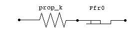
Defines a coupling between two masses, the coupling comprises a stiffness in series with a friction block. The property of the spring is read from a pre-defined property. The friction force is read as a variable or a data constant.
 coupl kf  `c_name' `body1' +-`a1 +-`b1 +-`h1
                    `body2' +-`a2 +-`b2 +-`h2
                     p_+-`prop_k' +-`Ffr0 `esys' `dire`
| c_name | = | Name of the coupling created. |
| body1 | = | Name of body no. 1, which the coupling is connected to. |
| a1,b1,h1 | = | The coupling's attachment coordinate in body 1, expressed in body 1's local coordinate system lsys. |
| body2 | = | Name of body no. 2 to which the coupling connects. |
| a2,b2,h2 | = | The coupling's attachment coordinate in body 2, expressed in body 2's local coordinate system lsys. |
| prop_k | = | Pre-defined stiffness property. The properties which are compatible with the coupling kf are p_lin and p_nlin. |
| Ffr0 | = | The friction force, if the force in the serial spring exceeds Ffr0 a sliding motion in the friction elements starts. |
| esys | = | The coordinate system in which the coupling force will be calculated. |
| dire | = | `x`, `y`, `z`, `f`, `k`, `p`, `c` Direction in esys, which the coupling acts in. In addition to the Cartesian coordinates, is the direction `c`. Direction `c` refers to the direction specified by the coupling's attachment points, i.e the force runs in the direction of the element. The transformation matrix is calculated when the coupling is read in the input reading phase of the program. The same transformation matrix is then used during the entire calculation. |
Variables generated in the main memory:
Input variables:
| c_name.l | = | Length of the coupling. The length is calculated in the same direction as the coupling's direction of action. |
| c_name.m1 | = | Mass number of body 1. |
| c_name.a1 | = | Attachment coordinate in x-direction on body 1. |
| c_name.b1 | = | Attachment coordinate in y-direction on body 1. |
| c_name.h1 | = | Attachment coordinate in z-direction on body 1. |
| c_name.m2 | = | Mass number of body 2. |
| c_name.a2 | = | Attachment coordinate in x-direction on body 2. |
| c_name.b2 | = | Attachment coordinate in y-direction on body 2. |
| c_name.h2 | = | Attachment coordinate in z-direction on body 2. |
| c_name.fr | = | The friction force Ffr0. |
Output variables:
| c_name.p | = | The position of the friction block. |
| c_name.d | = | Deformation of the stiffness. |
| c_name.F | = | The generated force in the coupling. |
| c_name.dx | = | The coupling's deformation in the x-direction. |
| c_name.dy | = | The coupling's deformation in the y-direction. |
| c_name.dz | = | The coupling's deformation in the z-direction. |
| c_name.df | = | The coupling's deformation in the f-direction. |
| c_name.dk | = | The coupling's deformation in the k-direction. |
| c_name.dp | = | The coupling's deformation in the p-direction. |
Force variables generated by the coupling:
| c_name.Fx | = | In the x-direction of esys. |
| c_name.Fy | = | In the y-direction of esys. |
| c_name.Fz | = | In the z-direction of esys. |
| c_name.Mf | = | In the f-direction of esys. |
| c_name.Mk | = | In the k-direction of esys. |
| c_name.Mp | = | In the p-direction of esys. |
Generated force variables on connected bodies:
| c_name.F1x | = | Force acting on body #1 in the x-direction of body #1's lsys. |
| c_name.F1y | = | Force acting on body #1 in the y-direction of body #1's lsys. |
| c_name.F1z | = | Force acting on body #1 in the z-direction of body #1's lsys. |
| c_name.M1f | = | Moment acting on body #1 in the f-direction of body #1's lsys. |
| c_name.M1k | = | Moment acting on body #1 in the k-direction of body #1's lsys. |
| c_name.M1p | = | Moment acting on body #1 in the p-direction of body #1's lsys. |
| c_name.F2x | = | Force acting on body #2 in the x-direction of body #2's lsys. |
| c_name.F2y | = | Force acting on body #2 in the y-direction of body #2's lsys. |
| c_name.F2z | = | Force acting on body #2 in the z-direction of body #2's lsys. |
| c_name.M2f | = | Moment acting on body #2 in the f-direction of body #2's lsys. |
| c_name.M2k | = | Moment acting on body #2 in the k-direction of body #2's lsys. |
| c_name.M2p | = | Moment acting on body #2 in the p-direction of body #2's lsys. |
The force in the spring prop_k is serial-coupled with the friction block Ffr0, which means that the coupling force through the kf-element is the same for the spring part as in the friction part. If the deformations of the ends of the kf-element are smaller than Ffr0/prop_k, no sliding motion will take place in the friction block, instead all motion will take place elastically in the spring part. If the deformation of the kf-element exceeds Ffr0/prop_k, the friction block will move the stretch required to ensure that the force over the spring part does not exceed the force Ffr0.
| – | This coupling can be used to generate all types of friction couplings, where the motion only occurs in one degree of freedom. |
| – | The coupling is convenient for generating a model of a flat center plate between bolster and carbody, whose only degree of freedom is a yawing motion. |
Defines a coupling between two masses, the coupling comprises a stiffness in series with a friction block. Similar to coupling kf, but coupling kf_l is defined with the angles fi,chi & psi relative to the coordinate system.
 coupl kf_l  `c_name' `body1' +-`a1 +-`b1 +-`h1
                      `body2' +-`a2 +-`b2 +-`h2
                       p_+-`prop_k' +-`Ffr0 `esys' `dire`
                       +-`fi +-`chi +-`psi
| c_name | = | Name of the coupling created. |
| body1 | = | Name of body no. 1, which the coupling is connected to. |
| a1,b1,h1 | = | The coupling's attachment coordinate in body 1, expressed in body 1's local coordinate system lsys. |
| body2 | = | Name of body no. 2 to which the coupling connects. |
| a2,b2,h2 | = | The coupling's attachment coordinate in body 2, expressed in body 2's local coordinate system lsys. |
| prop_k | = | Pre-defined stiffness property. The properties which are compatible with the coupling kf are p_lin and p_nlin. |
| Ffr0 | = | The friction force, if the force in the serial spring exceeds Ffr0 a sliding motion in the friction elements starts. |
| esys | = | The coordinate system in which the coupling force will be calculated. |
| dire | = | `x`, `y`, `z`, `f`, `k`, `p` Direction in esys, which the coupling acts in. |
| fi,chi,psi | = | The rotation angles from the coordinate system esys to the rotated position of the kf_l-coupling. |
Variables generated in the main memory are the same as for coupling kf.
The force in the spring prop_k is serial-coupled with the friction block Ffr0, which means that the coupling force through the kf-element is the same for the spring part as in the friction part. If the deformations of the ends of the kf-element are smaller than Ffr0/prop_k, no sliding motion will take place in the friction block, instead all motion will take place elastically in the spring part. If the deformation of the kf-element exceeds Ffr0/prop_k, the friction block will move the stretch required to ensure that the force over the spring part does not exceed the force Ffr0.
| – | In addition to coupl kf, coupl kf_l handles surfaces rotated relative to the esys coordinate system. |
Defines a coupling between two masses, the coupling comprises a stiffness in series with a friction block. The kf_r coupling is very similar to the kf_l coupling, but the kf_r-coupling handles large angles. The description of input data for the kf_r coupling can be found under kf_l.
Reference Manuals Calc menu Input Data Menu Coupl Menu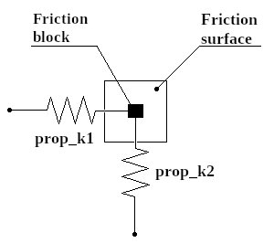
Defines a coupling between two masses, the coupling consists of two perpendicular stiffnesses connected to a friction block. The friction block will move on a two-dimensional surface, guided by the total force produced by the two stiffnesses. The total force from the two springs is calculated according to:
\( F_{tot}= \sqrt{ F_{k1}^2 + F_{k2}^2 } \)
A two-dimensional friction block is defined in the input data command:
 coupl kf2  `c_name' `body1' +-`a1 +-`b1 +-`h1
                     `body2' +-`a2 +-`b2 +-`h2
                      p_+-`prop_k1' p_+-`prop_k2'  +-`Ffr0 `esys' `dire1` `dire2`
| c_name | = | Name of the coupling created. |
| body1 | = | Name of body no. 1, which the coupling is connected to. |
| a1,b1,h1 | = | The coupling's attachment coordinate in body 1, expressed in body 1's local coordinate system lsys. |
| body2 | = | Name of body no. 2 to which the coupling connects. |
| a2,b2,h2 | = | The coupling's attachment coordinate in body 2, expressed in body 2's local coordinate system lsys. |
| prop_k1 | = | Pre-defined stiffness property in direction 1. In present release it is only possible to use property p_lin. |
| prop_k2 | = | Pre-defined stiffness property in direction 2. In present release it is only possible to use property p_lin. |
| Ffr0 | = | The friction force. (Friction moment if the direction of action is f, k or p) |
| esys | = | The coordinate system in which the coupling force will be calculated. |
| dire1 | = | Direction of action for stiffness property 1, valid directions are x, y, z, f, k or p. |
| dire2 | = | Direction of action for stiffness property 2, valid directions are x, y, z, f, k or p. |
Variables generated in the main memory:
Input variables:
| c_name.m1 | = | Mass number of body 1. |
| c_name.a1 | = | Attachment coordinate in x-direction on body 1. |
| c_name.b1 | = | Attachment coordinate in y-direction on body 1. |
| c_name.h1 | = | Attachment coordinate in z-direction on body 1. |
| c_name.m2 | = | Mass number of body 2. |
| c_name.a2 | = | Attachment coordinate in x-direction on body 2. |
| c_name.b2 | = | Attachment coordinate in y-direction on body 2. |
| c_name.h2 | = | Attachment coordinate in z-direction on body 2. |
Output variables:
| c_name.p1 | = | The position of the friction block in direction 1. |
| c_name.p2 | = | The position of the friction block in direction 2. |
| c_name.d1 | = | Deformation of the stiffness 1. |
| c_name.d2 | = | Deformation of the stiffness 2. |
| c_name.dx | = | The coupling's deformation in the x-direction. |
| c_name.dy | = | The coupling's deformation in the y-direction. |
| c_name.dz | = | The coupling's deformation in the z-direction. |
| c_name.df | = | The coupling's deformation in the f-direction. |
| c_name.dk | = | The coupling's deformation in the k-direction. |
| c_name.dp | = | The coupling's deformation in the p-direction. |
Force variables generated by the coupling:
| c_name.Fx | = | In the x-direction of esys. |
| c_name.Fy | = | In the y-direction of esys. |
| c_name.Fz | = | In the z-direction of esys. |
| c_name.Mf | = | In the f-direction of esys. |
| c_name.Mk | = | In the k-direction of esys. |
| c_name.Mp | = | In the p-direction of esys. |
Generated force variables on connected bodies:
| c_name.F1x | = | Force acting on body #1 in the x-direction of body #1's lsys. |
| c_name.F1y | = | Force acting on body #1 in the y-direction of body #1's lsys. |
| c_name.F1z | = | Force acting on body #1 in the z-direction of body #1's lsys. |
| c_name.M1f | = | Moment acting on body #1 in the f-direction of body #1's lsys. |
| c_name.M1k | = | Moment acting on body #1 in the k-direction of body #1's lsys. |
| c_name.M1p | = | Moment acting on body #1 in the p-direction of body #1's lsys. |
| c_name.F2x | = | Force acting on body #2 in the x-direction of body #2's lsys. |
| c_name.F2y | = | Force acting on body #2 in the y-direction of body #2's lsys. |
| c_name.F2z | = | Force acting on body #2 in the z-direction of body #2's lsys. |
| c_name.M2f | = | Moment acting on body #2 in the f-direction of body #2's lsys. |
| c_name.M2k | = | Moment acting on body #2 in the k-direction of body #2's lsys. |
| c_name.M2p | = | Moment acting on body #2 in the p-direction of body #2's lsys. |
| – | This coupling can be used to generate all types of friction couplings, where the motion is two-dimensional. |
| – | The coupling is convenient for generating models of the friction wedges in a three-piece bogie, or the friction surfaces in the primary suspension of a Y-25 bogie. |
Defines a coupling between two masses, the coupling consists of two perpendicular stiffnesses connected to a friction block. The kf2_l coupling is very similar to the kf2 coupling. In addition to the kf2 coupling kf2_l can also take into consideration a small rotation.
 coupl kf2  `c_name' `body1' +-`a1 +-`b1 +-`h1
                     `body2' +-`a2 +-`b2 +-`h2
                      p_+-`prop_k1' p_+-`prop_k2' +-`Ffr0    `esys' `dire1` `dire2`
                     `fi       `chi        `psi
Coupling kf2_l have the following three extra input parameters:
| fi | = | Positive rotation around the X-axis. |
| chi | = | Positive rotation around the Y-axis. |
| psi | = | Positive rotation around the Z-axis. |
The same output variables as for kf2 are beeing created.
Reference Manuals Calc menu Input Data Menu Coupl MenuDefines a coupling between two masses, the coupling comprises a stiffness in series with a friction block. The kf2_r coupling is very similar to the kf2_l coupling, the only difference is that the kf2_r coupling handles large angles. The description of input data for the kf2_r coupling can be found under kf2_l.
Reference Manuals Calc menu Input Data Menu Coupl MenuDefines a coupling between two masses, the coupling consists of three perpendicular stiffnesses connected to a friction block. The friction block will move on a three-dimensional surface, guided by the total force produced by the three stiffnesses.
 coupl kf3  `c_name' `body1' +-`a1 +-`b1 +-`h1
                     `body2' +-`a2 +-`b2 +-`h2
                     `prop_k1' `prop_k2' `prop_k3' +-`Ffr0
                     `esys'    `dire1`   `dire2`   `dire3`
| c_name | = | Name of the coupling created. |
| body1 | = | Name of body no. 1, which the coupling is connected to. |
| a1,b1,h1 | = | The coupling's attachment coordinate in body 1, expressed in body 1's local coordinate system lsys. |
| body2 | = | Name of body no. 2 to which the coupling connects. |
| a2,b2,h2 | = | The coupling's attachment coordinate in body 2, expressed in body 2's local coordinate system lsys. |
| prop_k1 | = | Pre-defined stiffness property in direction 1. In present release it is only possible to use property p_lin. |
| prop_k2 | = | Pre-defined stiffness property in direction 2. In present release it is only possible to use property p_lin. |
| prop_k3 | = | Pre-defined stiffness property in direction 3. In present release it is only possible to use property p_lin. |
| Ffr0 | = | Friction force. (Friction torque if the direction of action is f, k or p) |
| esys | = | The coordinate system in which the coupling force will be calculated. |
| dire1 | = | Direction of action for stiffness property 1, valid directions are x, y, z, f, k & p. |
| dire2 | = | Direction of action for stiffness property 2, valid directions are x, y, z, f, k & p. |
| dire3 | = | Direction of action for stiffness property 3, valid directions are x, y, z, f, k & p. |
Variables generated in the main memory:
Input variables:
| c_name.m1 | = | Mass number of body 1. |
| c_name.a1 | = | Attachment coordinate in x-direction on body 1. |
| c_name.b1 | = | Attachment coordinate in y-direction on body 1. |
| c_name.h1 | = | Attachment coordinate in z-direction on body 1. |
| c_name.m2 | = | Mass number of body 2. |
| c_name.a2 | = | Attachment coordinate in x-direction on body 2. |
| c_name.b2 | = | Attachment coordinate in y-direction on body 2. |
| c_name.h2 | = | Attachment coordinate in z-direction on body 2. |
Output variables:
| c_name.p1 | = | The position of the friction block in direction 1. |
| c_name.p2 | = | The position of the friction block in direction 2. |
| c_name.p3 | = | The position of the friction block in direction 3. |
| c_name.d1 | = | Deformation of the stiffness 1. |
| c_name.d2 | = | Deformation of the stiffness 2. |
| c_name.d3 | = | Deformation of the stiffness 3. |
| c_name.dx | = | The coupling's deformation in the x-direction. |
| c_name.dy | = | The coupling's deformation in the y-direction. |
| c_name.dz | = | The coupling's deformation in the z-direction. |
| c_name.df | = | The coupling's deformation in the f-direction. |
| c_name.dk | = | The coupling's deformation in the k-direction. |
| c_name.dp | = | The coupling's deformation in the p-direction. |
Force variables generated by the coupling:
| c_name.Fx | = | In the x-direction of esys. |
| c_name.Fy | = | In the y-direction of esys. |
| c_name.Fz | = | In the z-direction of esys. |
| c_name.Mf | = | In the f-direction of esys. |
| c_name.Mk | = | In the k-direction of esys. |
| c_name.Mp | = | In the p-direction of esys. |
Generated force variables on connected bodies:
| c_name.F1x | = | Force acting on body #1 in the x-direction of body #1's lsys. |
| c_name.F1y | = | Force acting on body #1 in the y-direction of body #1's lsys. |
| c_name.F1z | = | Force acting on body #1 in the z-direction of body #1's lsys. |
| c_name.M1f | = | Moment acting on body #1 in the f-direction of body #1's lsys. |
| c_name.M1k | = | Moment acting on body #1 in the k-direction of body #1's lsys. |
| c_name.M1p | = | Moment acting on body #1 in the p-direction of body #1's lsys. |
| c_name.F2x | = | Force acting on body #2 in the x-direction of body #2's lsys. |
| c_name.F2y | = | Force acting on body #2 in the y-direction of body #2's lsys. |
| c_name.F2z | = | Force acting on body #2 in the z-direction of body #2's lsys. |
| c_name.M2f | = | Moment acting on body #2 in the f-direction of body #2's lsys. |
| c_name.M2k | = | Moment acting on body #2 in the k-direction of body #2's lsys. |
| c_name.M2p | = | Moment acting on body #2 in the p-direction of body #2's lsys. |
| – | Spherical centerplates. |
Defines a one-dimensional coupling between two masses. The coupling comprises three parallel coupled parts:
| 1) | Elastic part: | Linear spring in the stiffness ke |
| 2) | Friction part: | Smooth Coulomb friction, parameters Ffm and x2 |
| 3) | Viscous part: | Linear viscous damper, c , in series with a linear spring, kv |
The parameters are taken from a pre-defined property defined in
coupl p_kfrkc.
The couplings which have direction c or cu may not have the length 0(zero),
as the value zero does not have a direction.
The theories of the kfrkc-coupling was developed by Mats Berg, Department of Vehicle Engineering, Royal Institute of Technology, Sweden. A detailed description of the coupling can be found in the report A rubber spring model for dynamic analysis of rail vehicles, ISSN 1103-470X, ISRN KTH/FKT/FR-95/53-SE.
 coupl kfrkc  `c_name' `body1' +-`a1 +-`b1 +-`h1
                       `body2' +-`a2 +-`b2 +-`h2
                       `p_kfrkc' `esys' `dire`
| c_name | = | Name of the coupling created. |
| body1 | = | Name of body no. 1, which the coupling is connected to. |
| a1,b1,h1 | = | The coupling's attachment coordinate in body 1, expressed in body 1's local coordinate system lsys. |
| body2 | = | Name of body no. 2 to which the coupling connects. |
| a2,b2,h2 | = | The coupling's attachment coordinate in body 2, expressed in body 2's local coordinate system lsys. |
| p_kfrkc | = | Pre-defined property. The only property which complies with the coupling kfrkc is p_kfrkc. |
| esys | = | The coordinate system in which the coupling force will be calculated. |
| dire | = | `x`, `y`, `z`, `f`, `k`, `p`, `c` Direction in esys, which the coupling acts in. In addition to the Cartesian coordinates, there is the direction `c`. Direction `c` refers to the directions specified by the coupling's attachment points, i.e the force runs in the direction of the element. The transformation matrix is calculated when the coupling is read in the input reading phase of the program. The same transformation matrix is then used during the entire calculation. |
Variables generated in the main memory:
Input variables:
| c_name.l | = | Length of the coupling. The length is calculated in the same direction as the coupling's direction of action. |
| c_name.m1 | = | Mass number of body 1. |
| c_name.a1 | = | Attachment coordinate in x-direction on body 1. |
| c_name.b1 | = | Attachment coordinate in y-direction on body 1. |
| c_name.h1 | = | Attachment coordinate in z-direction on body 1. |
| c_name.m2 | = | Mass number of body 2. |
| c_name.a2 | = | Attachment coordinate in x-direction on body 2. |
| c_name.b2 | = | Attachment coordinate in y-direction on body 2. |
| c_name.h2 | = | Attachment coordinate in z-direction on body 2. |
Output variables:
| c_name.d | = | Deformation over the coupling. |
| c_name.F | = | The generated force in the coupling. |
| c_name.fe | = | The generated force in the elastic part of the coupling. |
| c_name.ff | = | The generated force in the friction part of the coupling. |
| c_name.fv | = | The generated force in the viscous part of the coupling. |
| c_name.dx | = | The coupling's deformation in the x-direction. |
| c_name.dy | = | The coupling's deformation in the y-direction. |
| c_name.dz | = | The coupling's deformation in the z-direction. |
| c_name.df | = | The coupling's deformation in the f-direction. |
| c_name.dk | = | The coupling's deformation in the k-direction. |
| c_name.dp | = | The coupling's deformation in the p-direction. |
Force variables generated by the coupling:
| c_name.Fx | = | In the x-direction of esys. |
| c_name.Fy | = | In the y-direction of esys. |
| c_name.Fz | = | In the z-direction of esys. |
| c_name.Mf | = | In the f-direction of esys. |
| c_name.Mk | = | In the k-direction of esys. |
| c_name.Mp | = | In the p-direction of esys. |
Generated force variables on connected bodies:
| c_name.F1x | = | Force acting on body #1 in the x-direction of body #1's lsys. |
| c_name.F1y | = | Force acting on body #1 in the y-direction of body #1's lsys. |
| c_name.F1z | = | Force acting on body #1 in the z-direction of body #1's lsys. |
| c_name.M1f | = | Moment acting on body #1 in the f-direction of body #1's lsys. |
| c_name.M1k | = | Moment acting on body #1 in the k-direction of body #1's lsys. |
| c_name.M1p | = | Moment acting on body #1 in the p-direction of body #1's lsys. |
| c_name.F2x | = | Force acting on body #2 in the x-direction of body #2's lsys. |
| c_name.F2y | = | Force acting on body #2 in the y-direction of body #2's lsys. |
| c_name.F2z | = | Force acting on body #2 in the z-direction of body #2's lsys. |
| c_name.M2f | = | Moment acting on body #2 in the f-direction of body #2's lsys. |
| c_name.M2k | = | Moment acting on body #2 in the k-direction of body #2's lsys. |
| c_name.M2p | = | Moment acting on body #2 in the p-direction of body #2's lsys. |
The six input data parameters F0, ke, x2, Ffm, kv and c are described in detail under the property p_kfrkc. The coupling is non-linear due the smooth friction part of the coupling. On linearization in MODAL and FRESP, the friction part gives the stiffness Ffm/x2, but no energy dissipation (friction damping). In time simulation (TSIM), the effective stiffness of the coupling will be dependent on the displacement amplitude (relative to a static or quasistatical position). At small amplitudes, the total stiffness will asymptotically be Ffm/x2. At large amplitudes, the total stiffness will asymptotically be 0. The viscous part of the coupling will give a frequency dependent behavior in the property of the coupling.
| – | Smooth friction. |
| – | Rubber suspension element. |
Defines a coupling between two masses, the coupling comprises a stiffness in series with a friction damper. The stiffness of the upper side of the hysteresis loop is ku. The stiffness of the lower side of the hysteresis loop is kl. The friction damping is of type smooth friction and is defined by the stiffnesses in the end points dFA and dFB. The magnitude of the friction force follows an exponential function.
Following diagram shows the the force-displacement relationship for the coupling:
Input data for the coupling:
 coupl kf_exp1 `c_name' `body1' +-`a1 +-`b1 +-`h1
                        `body2' +-`a2 +-`b2 +-`h2
                        `esys' `dire`
                         +-`Fu +-`ku  +-`Fl +-`kl  +-`dFA +-`dFB
| c_name | = | Name of the coupling created. |
| body1 | = | Name of body no. 1, which the coupling is connected to. |
| a1,b1,h1 | = | The coupling's attachment coordinate in body 1, expressed in body 1's local coordinate system lsys. |
| body2 | = | Name of body no. 2 to which the coupling connects. |
| a2,b2,h2 | = | The coupling's attachment coordinate in body 2, expressed in body 2's local coordinate system lsys. |
| esys | = | The coordinate system in which the coupling force will be calculated. |
| dire | = | `x`, `y`, `z`, `f`, `k`, `p`, `c` Direction in esys, which the coupling acts in. In addition to the Cartesian coordinates, is the direction `c`. Direction `c` refers to the direction specified by the coupling's attachment points, i.e the force runs in the direction of the element. This direction is only valid if the coupling has a length. The transformation matrix is calculated when the coupling is read in the input reading phase of the program. The same transformation matrix is then used during the entire calculation. |
| Fu | = | Pre-load force at 0(zero) displacement, for the upper stiffness. |
| ku | = | The upper stiffness. |
| Fl | = | Pre-load force at 0(zero) displacement, for the lower stiffness. |
| kl | = | The lower stiffness. |
| dFA | = | The initial lower stiffness when the motion changes direction. |
| dFB | = | The initial upper stiffness when the motion changes direction. |
Variables generated in the main memory:
Input variables:
| c_name.l | = | Length of the coupling. The length is calculated in the same direction as the coupling's direction of action. |
| c_name.m1 | = | Mass number of body 1. |
| c_name.a1 | = | Attachment coordinate in x-direction on body 1. |
| c_name.b1 | = | Attachment coordinate in y-direction on body 1. |
| c_name.h1 | = | Attachment coordinate in z-direction on body 1. |
| c_name.m2 | = | Mass number of body 2. |
| c_name.a2 | = | Attachment coordinate in x-direction on body 2. |
| c_name.b2 | = | Attachment coordinate in y-direction on body 2. |
| c_name.h2 | = | Attachment coordinate in z-direction on body 2. |
Output variables:
| c_name.d | = | Deformation of the stiffness. |
| c_name.F | = | The generated force in the coupling. |
Force variables generated by the coupling:
| c_name.Fx | = | In the x-direction of esys. |
| c_name.Fy | = | In the y-direction of esys. |
| c_name.Fz | = | In the z-direction of esys. |
| c_name.Mf | = | In the f-direction of esys. |
| c_name.Mk | = | In the k-direction of esys. |
| c_name.Mp | = | In the p-direction of esys. |
Generated force variables on connected bodies:
| c_name.F1x | = | Force acting on body #1 in the x-direction of body #1's lsys. |
| c_name.F1y | = | Force acting on body #1 in the y-direction of body #1's lsys. |
| c_name.F1z | = | Force acting on body #1 in the z-direction of body #1's lsys. |
| c_name.M1f | = | Moment acting on body #1 in the f-direction of body #1's lsys. |
| c_name.M1k | = | Moment acting on body #1 in the k-direction of body #1's lsys. |
| c_name.M1p | = | Moment acting on body #1 in the p-direction of body #1's lsys. |
| c_name.F2x | = | Force acting on body #2 in the x-direction of body #2's lsys. |
| c_name.F2y | = | Force acting on body #2 in the y-direction of body #2's lsys. |
| c_name.F2z | = | Force acting on body #2 in the z-direction of body #2's lsys. |
| c_name.M2f | = | Moment acting on body #2 in the f-direction of body #2's lsys. |
| c_name.M2k | = | Moment acting on body #2 in the k-direction of body #2's lsys. |
| c_name.M2p | = | Moment acting on body #2 in the p-direction of body #2's lsys. |
| – | Leaf Spring. |
| – | UIC linkage, see example under: examples/main/calc/vehicle_11. |
Defines a coupling between two masses, the coupling comprises a stiffness in series with a friction damper. The stiffness of the coupling is defined by any property beginning with p_. The friction damping is of type smooth friction and is defined by the stiffnesses in the end points kfA and kfB, and the force amplitudes FfA and FfB. The magnitude of the friction force follows an exponential function.
Following diagram shows the the force-displacement relationship for the coupling when using stiffness property p_lin:
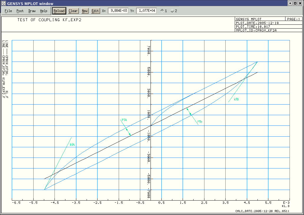
Following diagram shows the the force-displacement relationship for the coupling when using a non-linear property and setting
different values for kfA, kfB,FfA and FfB:
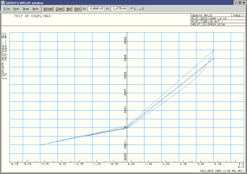
In diagram above the following input data has been used:
  coupl p_nlin  exp2_lin  0.  -.005 -1e3   .0 0.  .005 4e3
  coupl kf_exp2 Kfr_exp2 point1l -10.  2 2  point2l 10.  2 2  esys3 y  exp2_lin  2e6 1.  2e6 -1.
  func  operp   Kfr_exp2.FfA= 0.1 * ( Kfr_exp2.F + 1000 )
  func  operp   Kfr_exp2.FfB= -.1 * ( Kfr_exp2.F + 1000 )
Input data for the coupling:
 coupl kf_exp2 `c_name' `body1' +-`a1 +-`b1 +-`h1
                        `body2' +-`a2 +-`b2 +-`h2
                        `esys' `dire`
                         property   +-`kfA +-`FfA +-`kfB +-`FfB
| c_name | = | Name of the coupling created. |
| body1 | = | Name of body no. 1, which the coupling is connected to. |
| a1,b1,h1 | = | The coupling's attachment coordinate in body 1, expressed in body 1's local coordinate system lsys. |
| body2 | = | Name of body no. 2 to which the coupling connects. |
| a2,b2,h2 | = | The coupling's attachment coordinate in body 2, expressed in body 2's local coordinate system lsys. |
| esys | = | The coordinate system in which the coupling force will be calculated. |
| dire | = | `x`, `y`, `z`, `f`, `k`, `p`, Direction in esys, which the coupling acts in. |
| property | = | Pre-defined coupling property. |
| kfA | = | Additional stiffness due to friction when the spring starts to move in positive direction. |
| FfA | = | Maximum friction force when moving in positive direction. |
| kfB | = | Additional stiffness due to friction when the spring starts to move in negative direction. |
| FfB | = | Maximum friction force when moving in negative direction. |
Variables generated in the main memory:
Input variables:
| c_name.l | = | Length of the coupling. The length is calculated in the same direction as the coupling's direction of action. |
| c_name.m1 | = | Mass number of body 1. |
| c_name.a1 | = | Attachment coordinate in x-direction on body 1. |
| c_name.b1 | = | Attachment coordinate in y-direction on body 1. |
| c_name.h1 | = | Attachment coordinate in z-direction on body 1. |
| c_name.m2 | = | Mass number of body 2. |
| c_name.a2 | = | Attachment coordinate in x-direction on body 2. |
| c_name.b2 | = | Attachment coordinate in y-direction on body 2. |
| c_name.h2 | = | Attachment coordinate in z-direction on body 2. |
| c_name.kfA | = | Stiffness kfA. |
| c_name.FfA | = | Force FfA. |
| c_name.kfB | = | Stiffness kfB. |
| c_name.FfB | = | Force FfB. |
Output variables:
| c_name.d | = | Deformation of the stiffness. |
| c_name.Fe | = | The elastic force in the coupling. |
| c_name.Ff | = | The friction force in the coupling. |
| c_name.F | = | The total force in the coupling, in direction of action. |
Force variables generated by the coupling:
| c_name.Fx | = | In the x-direction of esys. |
| c_name.Fy | = | In the y-direction of esys. |
| c_name.Fz | = | In the z-direction of esys. |
| c_name.Mf | = | In the f-direction of esys. |
| c_name.Mk | = | In the k-direction of esys. |
| c_name.Mp | = | In the p-direction of esys. |
Generated force variables on connected bodies:
| c_name.F1x | = | Force acting on body #1 in the x-direction of body #1's lsys. |
| c_name.F1y | = | Force acting on body #1 in the y-direction of body #1's lsys. |
| c_name.F1z | = | Force acting on body #1 in the z-direction of body #1's lsys. |
| c_name.M1f | = | Moment acting on body #1 in the f-direction of body #1's lsys. |
| c_name.M1k | = | Moment acting on body #1 in the k-direction of body #1's lsys. |
| c_name.M1p | = | Moment acting on body #1 in the p-direction of body #1's lsys. |
| c_name.F2x | = | Force acting on body #2 in the x-direction of body #2's lsys. |
| c_name.F2y | = | Force acting on body #2 in the y-direction of body #2's lsys. |
| c_name.F2z | = | Force acting on body #2 in the z-direction of body #2's lsys. |
| c_name.M2f | = | Moment acting on body #2 in the f-direction of body #2's lsys. |
| c_name.M2k | = | Moment acting on body #2 in the k-direction of body #2's lsys. |
| c_name.M2p | = | Moment acting on body #2 in the p-direction of body #2's lsys. |
| – | Leaf Spring. |
| – | UIC linkage, see example under: examples/main/calc/vehicle_11. |
Defines a coupling between two masses, the coupling comprises a stiffness in series with a friction damper. The stiffness of the coupling is defined by any property beginning with p_. The friction damping is of type smooth friction and is very similar to kf_exp2. The main difference is how the smooth friction is defined. In this coupling the smooth friction is defined in the force amplitudes FfU and FfL, and the distances tauU and tauL. The smooth friction force has the shape of a exponential function like in a low-pass filter.
Input data for the coupling:
 coupl kf_exp3 `c_name' `body1' +-`a1 +-`b1 +-`h1
                        `body2' +-`a2 +-`b2 +-`h2
                        `esys' `dire`
                         property   +-`tauU +-`FfU +-`tauL +-`FfL
| c_name | = | Name of the coupling created. |
| body1 | = | Name of body no. 1, which the coupling is connected to. |
| a1,b1,h1 | = | The coupling's attachment coordinate in body 1, expressed in body 1's local coordinate system lsys. |
| body2 | = | Name of body no. 2 to which the coupling connects. |
| a2,b2,h2 | = | The coupling's attachment coordinate in body 2, expressed in body 2's local coordinate system lsys. |
| esys | = | The coordinate system in which the coupling force will be calculated. |
| dire | = | `x`, `y`, `z`, `f`, `k`, `p`, Direction in esys, which the coupling acts in. |
| property | = | Pre-defined coupling property. |
| tauU | = | Distance to where force FfU/2 is obtained. |
| FfU | = | Maximum friction force when moving in positive direction. |
| tauL | = | Distance to where force FfL/2 is obtained. |
| FfL | = | Maximum friction force when moving in negative direction. |
Variables generated in the main memory:
Input variables:
| c_name.l | = | Length of the coupling. The length is calculated in the same direction as the coupling's direction of action. |
| c_name.m1 | = | Mass number of body 1. |
| c_name.a1 | = | Attachment coordinate in x-direction on body 1. |
| c_name.b1 | = | Attachment coordinate in y-direction on body 1. |
| c_name.h1 | = | Attachment coordinate in z-direction on body 1. |
| c_name.m2 | = | Mass number of body 2. |
| c_name.a2 | = | Attachment coordinate in x-direction on body 2. |
| c_name.b2 | = | Attachment coordinate in y-direction on body 2. |
| c_name.h2 | = | Attachment coordinate in z-direction on body 2. |
| c_name.omegau | = | Angular frequency omegau. |
| c_name.Fdu | = | Force Fdu. |
| c_name.omegal | = | Angular frequency omegal. |
| c_name.Fdl | = | Force Fdl. |
Output variables:
| c_name.d | = | Deformation of the stiffness. |
| c_name.Fe | = | The elastic force in the coupling. |
| c_name.Ff | = | The friction force in the coupling. |
| c_name.F | = | The total force in the coupling, in direction of action. |
Force variables generated by the coupling:
| c_name.Fx | = | In the x-direction of esys. |
| c_name.Fy | = | In the y-direction of esys. |
| c_name.Fz | = | In the z-direction of esys. |
| c_name.Mf | = | In the f-direction of esys. |
| c_name.Mk | = | In the k-direction of esys. |
| c_name.Mp | = | In the p-direction of esys. |
Generated force variables on connected bodies:
| c_name.F1x | = | Force acting on body #1 in the x-direction of body #1's lsys. |
| c_name.F1y | = | Force acting on body #1 in the y-direction of body #1's lsys. |
| c_name.F1z | = | Force acting on body #1 in the z-direction of body #1's lsys. |
| c_name.M1f | = | Moment acting on body #1 in the f-direction of body #1's lsys. |
| c_name.M1k | = | Moment acting on body #1 in the k-direction of body #1's lsys. |
| c_name.M1p | = | Moment acting on body #1 in the p-direction of body #1's lsys. |
| c_name.F2x | = | Force acting on body #2 in the x-direction of body #2's lsys. |
| c_name.F2y | = | Force acting on body #2 in the y-direction of body #2's lsys. |
| c_name.F2z | = | Force acting on body #2 in the z-direction of body #2's lsys. |
| c_name.M2f | = | Moment acting on body #2 in the f-direction of body #2's lsys. |
| c_name.M2k | = | Moment acting on body #2 in the k-direction of body #2's lsys. |
| c_name.M2p | = | Moment acting on body #2 in the p-direction of body #2's lsys. |
Usage:
| – | Leaf Spring. |
| – | UIC linkage, see example under: examples/main/calc/vehicle_11. |
Connects a coupling to a flexible body.
Before this command can be given, both the flexible body and the coupling must
have been previously defined in the input data.
The modal shapes' values shall be given mass orthonormalized, i.e
| M | = | Mass matrix |
| x | = | Eigenvector |
| xT | = | The transpose of x |
Normally the user don't need to give these input manually, because this input data group can automatically be generated by the NPICK-program.
coupl m_flex_1 `c_name' `end` values
| c_name | = | Assigning a name to this property. |
| end | = | Specifies the end of the coupling for which the modal shapes shall be read. Input data parameter end can have two valid values `end_1` or `end_2'. `end_1` causes input reading of the eigenvectors for body1 and 'end_2' causes input reading of the eigenvectors for body2. |
| values | = |
Specification of the eigenvectors. If the coupling's work direction is set to `m`, the eigenvectors are given with 6 components per eigenfrequency, i.e. the input data is as follows: x1, y1, z1, f1, k1, p1, x2, y2, z2, f2, k2, p2, A total of n modal shapes. . . . . . . Number of modal shapes which . . . . . . shall be read, is controlled xn, yn, zn, fn, kn, pn, by `mass m_flex_1`. x1, y1, z1, x2, y2, z2, A total of n modal shapes. . . . . . . xn, yn, zn, If the coupling's work direction is given as `f`, `k` or `p`, the eigenvectors will given by 3 angle components per eigenfrequency, i.e. the input data is as follows: f1, k1, p1, f2, k2, p2, A total of n modal shapes. . . . . . . fn, kn, pn, Number of eigenfrequencies n is earlier defined in the `mass m_flex_1`- command. |
Variables generated in the main memory:
| c_name.x1 | = | Modal shape value, x-direction, eigenfrequency #1 |
| c_name.y1 | = | Modal shape value, y-direction, eigenfrequency #1 |
| c_name.z1 | = | Modal shape value, z-direction, eigenfrequency #1 |
| c_name.f1 | = | Modal shape value, f-direction, eigenfrequency #1 |
| . . . | = | . . . . . . . . |
| c_name.x2 | = | Modal shape value, x-direction, eigenfrequency #2 |
| . . . | = | . . . . . . . . |
| c_name.kn | = | Modal shape value, k-direction, eigenfrequency #n |
| c_name.pn | = | Modal shape value, p-direction, eigenfrequency #n |
| c_name1c1 | = | Generalized force on flexible mass end 1, eigenmode 1 |
| c_name1c2 | = | Generalized force on flexible mass end 1, eigenmode 2 |
| c_name1c3 | = | Generalized force on flexible mass end 1, eigenmode 3 |
| . . . | . | . . . etc. for all eigenfrequencies. |
| c_name2c1 | = | Generalized force on flexible mass end 2, eigenmode 1 |
| c_name2c2 | = | Generalized force on flexible mass end 2, eigenmode 2 |
| c_name2c3 | = | Generalized force on flexible mass end 2, eigenmode 3 |
| . . . | . | . . . etc. for all eigenfrequencies. |
Connects a coupling to a flexible body.
Before this command can be given, both the flexible body and the coupling must
have been previously defined in the input data.
The modal shapes' values shall be given mass orthonormalized, i.e
| M | = | Mass matrix |
| x | = | Eigenvector |
| xT | = | The transpose of x |
 coupl m_flex_m6  `c_name'  `end`

                   nSec  xSec(1)       # Longitudinal positions where
                         xSec(2)       # the eigen modes are defined
                         . . .
                         xSec(nSec)

                         x(1,1), y(1,1), z(1,1), f(1,1), k(1,1), p(1,1),  # Position 1
                         x(2,1), y(2,1), z(2,1), f(2,1), k(2,1), p(2,1),  # A total of nFlex modal shapes.
                          .   .   .   .   .   .                           # Number of modal shapes is
                          .   .   .   .   .   .                           # defined in mass m_flex_1
                         x(nFlex,1), y(nFlex,1), z(nFlex,1), f(nFlex,1), k(nFlex,1), p(nFlex,1),

                         x(1,2), y(1,2), z(1,2), f(1,2), k(1,2), p(1,2),  # Position 2
                         x(2,2), y(2,2), z(2,2), f(2,2), k(2,2), p(2,2),
                          .   .   .   .   .   .
                          .   .   .   .   .   .
                         x(nFlex,2), y(nFlex,2), z(nFlex,2), f(nFlex,2), k(nFlex,2), p(nFlex,2),


                          .   .   .   .   .   .
                          .   .   .   .   .   .


                         x(1,nSec),y(1,nSec),z(1,nSec),f(1,nSec),k(1,nSec),p(1,nSec),  # Position nSec
                         x(2,nSec),y(2,nSec),z(2,nSec),f(2,nSec),k(2,nSec),p(2,nSec),
                          .   .   .   .   .   .
                          .   .   .   .   .   .
                         x(nFlex,nSec),y(nFlex,nSec),z(nFlex,nSec),f(nFlex,nSec),k(nFlex,nSec),p(nFlex,nSec)
| c_name | = | Assigning a name to this property. |
| end | = | Specifies the end of the coupling for which the modal shapes shall be read. Input data parameter end can have two valid values `end_1` or `end_2'. `end_1` causes input reading of the eigenvectors for body1 and 'end_2' causes input reading of the eigenvectors for body2. |
| nSec | = | Specifies number of sections/positions, where the modal shapes are given. When the attachment of a coupling is located in between two sections/positions, spline interpolation is taking place. |
| xSec(1:nSec) | = | Longitudinal positions of the sections/positions. |
| values | = |
Specification of the eigenvectors for all eigen values and in all sections/positions. The values are given in a 3D-matrix, where the first dimension is the direction of the modal shape x,y,z,f,k or p. The second dimension is the number of the eigen mode defined in a previous mass m_flex_1-command. The third dimension is the section/position. |
Variables generated in the main memory:
| c_name1c1 | = | Generalized force on flexible mass end 1, eigenmode 1 |
| c_name1c2 | = | Generalized force on flexible mass end 1, eigenmode 2 |
| c_name1c3 | = | Generalized force on flexible mass end 1, eigenmode 3 |
| . . . | . | . . . etc. for all eigenfrequencies. |
| c_name2c1 | = | Generalized force on flexible mass end 2, eigenmode 1 |
| c_name2c2 | = | Generalized force on flexible mass end 2, eigenmode 2 |
| c_name2c3 | = | Generalized force on flexible mass end 2, eigenmode 3 |
| . . . | . | . . . etc. for all eigenfrequencies. |
Defines a coupling written by the user.
The properties of this coupling is given in a subroutine written by the user.
Up to ten user written subroutine can be feed into the CALC-program.
The #-sign indicates the number of the coupling.
The CALC-program calculates the displacement and speed of the two ends of the coupling,
so the user written subroutine only needs to calculate the force in the coupling.
The subroutine calculating the force is named cuser#.
The input reading subroutine for cuser# is named icusr#.
If no own user subroutines are supplied,
the calc-linking script will load dummy subroutines from the gen_calclib library.
The source code of the new subroutine shall be located in directory $gensys/code/calc/calc.
To compile an own written coupling, take the following steps:
sudo apt-get install g++
sudo apt-get install gfortran gfortran-4.7 libgfortran3 libgfortran-4.7-dev
sudo apt-get install gfortran-doc gfortran-4.7-doc
sudo apt-get install libreadline-dev
sudo apt-get install libncurses5-dev
sudo apt-get install libmotif-dev x11proto-print-dev
sudo apt-get install libxt-dev
sudo apt-get install libxp-dev
sudo apt-get install libxpm-dev
sudo apt-get install libxext-dev
sudo apt-get install libxmu-dev libxmu-headers
sudo apt-get install libgl1-mesa-dev
sudo apt-get install libglu1-mesa-dev
sudo apt-get install libxft-dev
sudo apt-get install libxaw7-dev
The following FORTRAN subroutine can be used as a template when writing own subroutines:
*cuser0
c     --------------------------------------------------------------------------
c0    User supplied coupling
c     --------------------------------------------------------------------------
      subroutine cuser0 (
     & icoupl, ! IN  Number of the coupling
     & delt,   ! IN  Deformation, if the coupling is one dimensional
     & vdelt,  ! IN  Speed of deformation, if the coupling is one dimensional
     & posb1,  ! IN  Position of attachment point body # 1 in esys
     & posb2,  ! IN  Position of attachment point body # 2 in esys
     & delta,  ! IN  Deformation (posb2-posb1), if the coupling has working direction m
     & velb1,  ! IN  Velcity of attachment point body # 1 in esys
     & velb2,  ! IN  Velcity of attachment point body # 2 in esys
     & vdelta, ! IN  Speed of deformation (velb2-velb1), if the coupling has working direction m
     & iforc,  ! OUT Indicator showing where the output force is stored
     &         !      iforc=1, the result is stored in forc
     &         !      iforc=2, the result is stored in force
     &         !      iforc=3, the result is stored in force1 and force2
     & forc,   ! OUT Force, if the coupling is one dimensional
     & force,  ! OUT Force, if the coupling has working direction m
     & force1, ! OUT Force on body #1, if the coupling has working direction m
     & force2) ! OUT Force on body #2, if the coupling has working direction m
c     --------------------------------------------------------------------------
      use calclib_decl_mod, only:
     &     mvar,                    ! Number of declared variables
     &     nvar,                    ! Number of read/created variables
     &     var,                     ! Main memory variables
     &     name,                    ! Main memory variable names
     &     ityp                     ! Type of variable
c     --------------------------------------------------------------------------
      implicit real(8) (a-h,o-z)
c     --------------------------------------------------------------------------
      integer,  intent (IN) :: icoupl
      real(8),  intent (IN) :: delt, vdelt
      real(8),  intent (IN) :: posb1(6), posb2(6), delta(6)
      real(8),  intent (IN) :: velb1(6), velb2(6), vdelta(6)
      integer,  intent(OUT) :: iforc
      real(8),  intent(OUT) :: forc
      real(8),  intent(OUT) :: force(6), force1(6), force2(6)
c     --------------------------------------------------------------------------
      include '../../interface.h'
      include '../../interface_calclib.h'
c     --------------------------------------------------------------------------
#ifdef MEM_SMALL
      include '../../calc/calc/mp_small.h'
#else
      include '../../calc/calc/mp_big.h'
#endif
c     --------------------------------------------------------------------------
c
c       time commons
      common /g_time/ time, timold, tdiff
c
c       coupl commons
      common /ncoupl/ ncoupl
      common /idat_c/ idat_c (kcoupl)
      common /indx_c/ indx_c (kcoupl)
c
      character(*), parameter :: subr= 'cuser0'
c     --------------------------------------------------------------------------

      ipdat_c= idat_c(icoupl)

c
c      Pick up property from memory
c      ============================
      iprop= nint (var(ipdat_c+15))
      call kforc1 (iprop, name(iprop+1), 1, delt, forc)

c
c      Pick up own defined data from memory
c      ====================================
      data1= var(ipdat_c+17)
      data2= var(ipdat_c+18)
      data3= var(ipdat_c+19)
      data4= var(ipdat_c+20)
      data5= var(ipdat_c+21)
      data6= var(ipdat_c+22)

c
c      Calculate force in own defined coupling
c      =======================================
      iforc= 1
      forc = forc + data2 - data1
c
c
      return
      end
The following FORTRAN subroutine can be used as a template when writing the input data reading subroutine:
*icusr#
c     --------------------------------------------------------------------------
c0     User defined coupling. Input data reading
c     --------------------------------------------------------------------------
      subroutine icusr0 (
     & icoupl, ! IN  Number of the coupling
     & c_name, ! IN  Name of coupling
     & c_type) ! IN  Type of coupling
c     --------------------------------------------------------------------------
      use calclib_decl_mod, only:
     &     mvar,                    ! Number of declared variables
     &     nvar,                    ! Number of read/created variables
     &     var,                     ! Main memory variables
     &     name,                    ! Main memory variable names
     &     ityp                     ! Type of variable
c     --------------------------------------------------------------------------
      implicit real(8) (a-h,o-z)
c     --------------------------------------------------------------------------
      integer,       intent( IN) :: icoupl
      character(24), intent( IN) :: c_type, c_name
c     --------------------------------------------------------------------------
      include '../../interface.h'
      include '../../interface_calclib.h'
c     --------------------------------------------------------------------------
#ifdef MEM_SMALL
      include '../../calc/calc/mp_small.h'
#else
      include '../../calc/calc/mp_big.h'
#endif
c     --------------------------------------------------------------------------
c
c       constant commons
      common /blank / blank;            character(132)  :: blank
      common /crikt / crikt;            character(1)    :: crikt(6)     !! Translates from numbers to 'x','y','z','f','k','p'
      common /pi    / pi, twopi
c
c       error commons
      common /ierfil/ ierfil
      common /ierror/ ierror
      common /nwarn / nwarn
      common /idebug/ idebug, ldebug, ioverw, iwcafi, icifa0, istore_ntime
c
c       read commons
      common /infile/ infile
      common /inread/ irad, indexa, indexb, indexe, indxbo, indxeo
      common /cdata / cdata;            character(132)  :: cdata
      common /rdata / rdata;            real(4)         :: rdata
      common /ddata / ddata;            real(8)         :: ddata
      character(132) :: rfile      ! Name of file currently reading from
      character(132) :: rsubsc     ! Name of substructure, if reading from a substructure
      common /rfile / rfile, rsubsc
c
c       coupl commons
      common /mcoupl/ mcoupl
      common /ncoupl/ ncoupl
      common /jcoupl/ jcoupl
      common /idat_c/ idat_c (kcoupl)
      common /indx_c/ indx_c (kcoupl)
c
c       local variables
      real(8)       :: deltc(3)
      character(24) :: char24, esys
      character( 2) :: dire1
      character(*), parameter  :: subr= 'icusr0'
c     --------------------------------------------------------------------------

c
c      Increase main memory if necessary
c      =======================================
      if (nvar+1000.ge.mvar) call gen_reallocate_var(1000, c_name, subr, *920)

c
c      Store data in main memory (Name and type of coupling)
c      =====================================================
      idat_c(icoupl)= nvar + 1
      ipdat_c= idat_c(icoupl)
      name(ipdat_c   )= c_name
      var (ipdat_c   )= dble(icoupl)
      name(ipdat_c+ 1)= c_type
      var (ipdat_c+ 1)= 0.d0
c
      l_name= len_trim(c_name)
      if (l_name.gt.20) call error_exit(subr, '             Too many characters in name of coupling '//trim(c_name))

c
c      Read mass #1 and the coordinates of its attachment point
c      ========================================================
      call read_a (char24, 24, 1, *920, *920)
      ipos= 0
      call find   (char24, ipos, subr, *920)
      im1 = nint( var(ipos) )
c
      name(ipdat_c+ 2)= c_name(1:l_name)//'.m1'
      var (ipdat_c+ 2)= dble(im1)
      name(ipdat_c+ 3)= blank(1:24)     ! Working direction
      var (ipdat_c+ 3)= 0.d0
c
      call read_var(1,0,1,1, ipdat_c+ 4,ipos, c_name(1:l_name)//'.a1', subr, *920)
      call read_var(1,0,1,1, ipdat_c+ 5,ipos, c_name(1:l_name)//'.b1', subr, *920)
      call read_var(1,0,1,1, ipdat_c+ 6,ipos, c_name(1:l_name)//'.h1', subr, *920)

c
c      Read mass #2 and the coordinates of its attachment point
c      ========================================================
      call read_a (char24, 24, 1, *920, *920)
      ipos= 0
      call find   (char24, ipos, subr, *920)
      im2 = nint( var(ipos) )
c
      name(ipdat_c+ 7)= c_name(1:l_name)//'.m2'
      var (ipdat_c+ 7)= dble(im2)
      name(ipdat_c+ 8)= blank(1:24)     ! Working direction
      var (ipdat_c+ 8)= 0.d0
c
      call read_var(1,0,1,1, ipdat_c+ 9,ipos, c_name(1:l_name)//'.a2', subr, *920)
      call read_var(1,0,1,1, ipdat_c+10,ipos, c_name(1:l_name)//'.b2', subr, *920)
      call read_var(1,0,1,1, ipdat_c+11,ipos, c_name(1:l_name)//'.h2', subr, *920)

c
c      Addresses to flexible masses
c      ============================
      name(ipdat_c+13)= 'modal_mass_1            '
      var (ipdat_c+13)=  0.d0
      name(ipdat_c+14)= 'modal_mass_2            '
      var (ipdat_c+14)=  0.d0

c
c      Read predefined property
c      ========================
      call read_u2(1, ddata, iadr, cdata, *920)
      if (iadr.eq.-7) then
       ipos= nint(ddata)
      else
       write(ierfil,*)
       write(ierfil,*) '***ERROR*** In '//subr
       write(ierfil,*) '            Unknown property '//trim(cdata)
       write(ierfil,*) '            has been read, iadr=', iadr
       goto 920
      endif
c
      name(ipdat_c+15)= ' '//cdata(1:23)
      var (ipdat_c+15)= dble(ipos)
      ityp(ipdat_c+15)= -1

c
c      Read esys to calculate deformations in.
c      =======================================
      call read_a (esys, 24, 1, *920, *920)
      ipos1= 0
      call find   (esys, ipos1, subr, *920)
      if (name(ipos1+1)(1:2).eq.'e_') then
       name(ipdat_c+16)= ' '//esys(1:23)
       var (ipdat_c+16)= var(ipos1)
       iesys= nint( var(ipos1) )
      else
       write(ierfil,'(a)') ' ',
     &   ' ***ERROR*** In '//subr,
     &   '             Cannot calculate deformations in coord. system '//trim(esys),
     &   '             The coordinate system must be an Euler system.'
       goto 920
      endif

c
c      Working direction of coupling.
c      ==============================
      call read_a (dire1, 2, 1, *920, *920)
      name(ipdat_c+ 3)= dire1
      name(ipdat_c+ 8)= dire1
c
      if (dire1.ne.'x ' .and. dire1.ne.'y ' .and. dire1.ne.'z ' .and.
     &    dire1.ne.'f ' .and. dire1.ne.'k ' .and. dire1.ne.'p ' .and.
     &    dire1.ne.'c ' .and. dire1.ne.'cu' .and. dire1.ne.'m ') then
       write(ierfil,'(a)') ' ',
     &   ' ***ERROR*** In '//subr,
     &   '             Unvalid working direction= '//dire1
       goto 920
      endif

c
c      Undeformed length of the coupling
c      =================================
      name(ipdat_c+12)= c_name(1:l_name)//'.l '
      if (dire1.eq.'x ' .or. dire1.eq.'y ' .or. dire1.eq.'z ' .or.
     &    dire1.eq.'c ' .or. dire1.eq.'cu') then
       call coupll (icoupl, iesys, im1, im2, deltc)
       var (ipdat_c+12)= sqrt(deltc(1)**2 + deltc(2)**2 + deltc(3)**2)
      else
       var (ipdat_c+12)= 0.d0
      endif

c
c      Read own user defined data
c      ===========================
      name(ipdat_c+17)= c_name(1:l_name)//'.d1'
      call read_u2(1, ddata, iadr, cdata, *920)
      if (iadr.le.-3) call error(cdata(1:12), subr, 8-iadr, *920)
      var (ipdat_c+17)= ddata
      ityp(ipdat_c+17)= iadr
c
      name(ipdat_c+18)= c_name(1:l_name)//'.d2'
      call read_u2(1, ddata, iadr, cdata, *920)
      if (iadr.le.-3) call error(cdata(1:12), subr, 8-iadr, *920)
      var (ipdat_c+18)= ddata
      ityp(ipdat_c+18)= iadr
c
      name(ipdat_c+19)= c_name(1:l_name)//'.d3'
      call read_u2(1, ddata, iadr, cdata, *920)
      if (iadr.le.-3) call error(cdata(1:12), subr, 8-iadr, *920)
      var (ipdat_c+19)= ddata
      ityp(ipdat_c+19)= iadr
c
      name(ipdat_c+20)= c_name(1:l_name)//'.d4'
      call read_u2(1, ddata, iadr, cdata, *920)
      if (iadr.le.-3) call error(cdata(1:12), subr, 8-iadr, *920)
      var (ipdat_c+20)= ddata
      ityp(ipdat_c+20)= iadr
c
      name(ipdat_c+21)= c_name(1:l_name)//'.d5'
      call read_u2(1, ddata, iadr, cdata, *920)
      if (iadr.le.-3) call error(cdata(1:12), subr, 8-iadr, *920)
      var (ipdat_c+21)= ddata
      ityp(ipdat_c+21)= iadr
c
      name(ipdat_c+22)= c_name(1:l_name)//'.d6'
      call read_u2(1, ddata, iadr, cdata, *920)
      if (iadr.le.-3) call error(cdata(1:12), subr, 8-iadr, *920)
      var (ipdat_c+22)= ddata
      ityp(ipdat_c+22)= iadr
c
      nvar= ipdat_c+22                  !! Address to last written address in memory

c
c      Reserve memory for results
c      ==========================
      if (nvar+25.ge.mvar) call gen_reallocate_var(25, c_name, subr, *920)
      indx_c(icoupl)= nvar + 1
c
      name(indx_c(icoupl)   )= c_name(1:l_name)//'.d '
      name(indx_c(icoupl)+ 1)= c_name(1:l_name)//'.F '
c
      name(indx_c(icoupl)+ 2)= c_name(1:l_name)//'.F1x'
      name(indx_c(icoupl)+ 3)= c_name(1:l_name)//'.F1y'
      name(indx_c(icoupl)+ 4)= c_name(1:l_name)//'.F1z'
      name(indx_c(icoupl)+ 5)= c_name(1:l_name)//'.M1f'
      name(indx_c(icoupl)+ 6)= c_name(1:l_name)//'.M1k'
      name(indx_c(icoupl)+ 7)= c_name(1:l_name)//'.M1p'
      name(indx_c(icoupl)+ 8)= c_name(1:l_name)//'.F2x'
      name(indx_c(icoupl)+ 9)= c_name(1:l_name)//'.F2y'
      name(indx_c(icoupl)+10)= c_name(1:l_name)//'.F2z'
      name(indx_c(icoupl)+11)= c_name(1:l_name)//'.M2f'
      name(indx_c(icoupl)+12)= c_name(1:l_name)//'.M2k'
      name(indx_c(icoupl)+13)= c_name(1:l_name)//'.M2p'
      name(indx_c(icoupl)+14)= c_name(1:l_name)//'.dx'
      name(indx_c(icoupl)+15)= c_name(1:l_name)//'.dy'
      name(indx_c(icoupl)+16)= c_name(1:l_name)//'.dz'
      name(indx_c(icoupl)+17)= c_name(1:l_name)//'.df'
      name(indx_c(icoupl)+18)= c_name(1:l_name)//'.dk'
      name(indx_c(icoupl)+19)= c_name(1:l_name)//'.dp'
      name(indx_c(icoupl)+20)= c_name(1:l_name)//'.Fx'
      name(indx_c(icoupl)+21)= c_name(1:l_name)//'.Fy'
      name(indx_c(icoupl)+22)= c_name(1:l_name)//'.Fz'
      name(indx_c(icoupl)+23)= c_name(1:l_name)//'.Mf'
      name(indx_c(icoupl)+24)= c_name(1:l_name)//'.Mk'
      name(indx_c(icoupl)+25)= c_name(1:l_name)//'.Mp'
      nvar= indx_c(icoupl)+25
c
c
 1000 return
 920  ierror= ierror + 1        !! *** ERROR ***
 910  continue                  !!  * Warning *
      goto 1000
c
      end
When you have written the code for your new coupling, it is a good idea to test its output. With this simple input data file you can apply a controlled displacement over the coupling:
#
#
  head 2 "Test of couplings"
#
  idebug= 0
  tsim_param  e1   tstart=0.  tstop= 1.6 tout=0.005 tstep=0.005
  quasi_param LineSearch_1  1.e-7, 1.e-6 0.005 0.00005 60 40

###
###  Create esys and lsys
###  -----------------------------------------------------------
  func intpl_r krok_R1  -200 0   0 0
  func intpl_r krok_fi1 -200 0   0 0
  func intpl_r krok_z1  -200 0   0 0
  func const   V0  50
  lsys e_var_bend  esys3  V0    0   krok_R1  krok_fi1  krok_z1
  lsys l_local     lsys31 esys3  10 0 0
  lsys l_local     lsys32 esys3 -10 0 0

###
###  Create masses
###  -----------------------------------------------------------
  mass   fixpoint_6   point1l  lsys31  0 0 0
  mass   fixpoint_6   point2l  lsys32  0 0 0

###
###  Create a sine-wave 2(Hz)
###  -----------------------------------------------------------
  func operp ampl 0.070 * sin( 6.28318531 * 2 * time )

###
###  Create a triangular wave 5(Hz) amplitude 10(mm)
###  -----------------------------------------------------------
# func operp signal    2000 * cos( 6.28318531 *  4 * time )
# func const ulevel= 0.02
# func const llevel= -.05
# func u_lim signal    ulevel
# func l_lim signal    llevel
# func integ ampl      signal
# if_then time .gt. 1.2
#  func copy  ulevel= 0.05
#  func copy  llevel= -.02
# endif

###
###  Move the mass(es)
###  -----------------------------------------------------------
# no_warning func copy        point1l.x    -ampl
# no_warning func copy        point2l.x     ampl
  no_warning func copy        point1l.y     ampl
  no_warning func copy        point2l.y    -ampl
#
  no_warning func deriv       point1l.vx    point1l.x
  no_warning func deriv       point2l.vx    point2l.x
  no_warning func deriv       point1l.vy    point1l.y
  no_warning func deriv       point2l.vy    point2l.y
  no_warning func deriv       point1l.vz    point1l.z
  no_warning func deriv       point2l.vz    point2l.z
  no_warning func deriv       point1l.vf    point1l.f
  no_warning func deriv       point2l.vf    point2l.f
  no_warning func deriv       point1l.vk    point1l.k
  no_warning func deriv       point2l.vk    point2l.k
  no_warning func deriv       point1l.vp    point1l.p
  no_warning func deriv       point2l.vp    point2l.p

###
###  Create Spring
###  -----------------------------------------------------------
#                          coupl `cuser0`       Central coupler
# -------------------------------------------------------------
  coupl p_lin  ky4p  0.  5e6
  coupl cuser0 cuser0  point1l -10.  0 0   point2l 10. 0 0  ky4p esys3 y
#
#       d1      d2      d3      d4      d5      d6
        1e6     2e6     3e6     4e6     5e6     6e6
#
  s_var sngl cuser0.d1
  s_var sngl cuser0.d2
  s_var sngl cuser0.d3
  s_var sngl cuser0.d4
  s_var sngl cuser0.d5
  s_var sngl cuser0.d6

#
#  coupl `k`
# ----------------------------------------------------------
  coupl p_lin kyp  0.  5e6
  coupl k     Kl   point1l -10 2 2  point2l 10 2 2  kyp esys3 y

#
#  coupl `c`
# ----------------------------------------------------------
  coupl p_lin cyp  0.  1e6
  coupl c     Cl   point1l -10 2 2  point2l 10 2 2  cyp esys3 y

###
###  Store results
###  -----------------------------------------------------------
  substruct store_kz [  # $1= Name of coupling
   s_var sngl $1.d s_var sngl $1.F  s_var sngl $1.l
#
   s_var sngl $1.dx  s_var sngl $1.dy  s_var sngl $1.dz
   s_var sngl $1.df  s_var sngl $1.dk  s_var sngl $1.dp
   s_var sngl $1.Fx  s_var sngl $1.Fy  s_var sngl $1.Fz
   s_var sngl $1.Mf  s_var sngl $1.Mk  s_var sngl $1.Mp
#
   s_var sngl $1.F1x  s_var sngl $1.F2x
   s_var sngl $1.F1y  s_var sngl $1.F2y
   s_var sngl $1.F1z  s_var sngl $1.F2z
   s_var sngl $1.M1f  s_var sngl $1.M2f
   s_var sngl $1.M1k  s_var sngl $1.M2k
   s_var sngl $1.M1p  s_var sngl $1.M2p
  ]
  in_substruct store_kz [ cuser0  ]
  in_substruct store_kz [ Kl      ]
  in_substruct store_kz [ Cl      ]

  s_var sngl point1l.x   s_var sngl point2l.x
  s_var sngl point1l.vx  s_var sngl point2l.vx
  s_var sngl point1l.Fx  s_var sngl point2l.Fx
  s_var sngl point1l.y   s_var sngl point2l.y
  s_var sngl point1l.vy  s_var sngl point2l.vy
  s_var sngl point1l.Fy  s_var sngl point2l.Fy
  s_var sngl point1l.z   s_var sngl point2l.z
  s_var sngl point1l.vz  s_var sngl point2l.vz
  s_var sngl point1l.Fz  s_var sngl point2l.Fz
  s_var sngl point1l.f   s_var sngl point2l.f
  s_var sngl point1l.vf  s_var sngl point2l.vf
  s_var sngl point1l.Mf  s_var sngl point2l.Mf
  s_var sngl point1l.k   s_var sngl point2l.k
  s_var sngl point1l.vk  s_var sngl point2l.vk
  s_var sngl point1l.Mk  s_var sngl point2l.Mk
  s_var sngl point1l.p   s_var sngl point2l.p
  s_var sngl point1l.vp  s_var sngl point2l.vp
  s_var sngl point1l.Mp  s_var sngl point2l.Mp

  eof
Reference Manuals
Calc menu
Input Data Menu
Coupl Menu